
What a Failed Transformer Insulation Test Really Means
What happens if a transformer insulation test fails? The short answer is that the transformer should not be casually returned to service. A poor insulation-resistance result can point to moisture ingress, surface contamination, insulation aging, a damaged bushing, internal lead problems, or an error in the test setup itself. The result does not automatically prove that the active part is beyond repair, but it does mean the asset’s dielectric condition needs to be understood before energization.
This is where experienced maintenance teams separate a useful diagnostic from a costly overreaction. An insulation test is not a pass/fail sticker in isolation. Its value comes from the condition under which it was taken, the test voltage and duration, temperature, humidity, transformer design, previous readings, and whether the unit was properly isolated. A reading that looks alarming on a wet morning at an outdoor substation may have a very different meaning from the same reading on a dry, recently processed transformer in a controlled workshop.
For utilities, industrial plants, renewable-energy sites, and grid contractors, the immediate priority is simple: protect people, prevent an avoidable dielectric failure, and preserve the evidence needed to identify the actual cause. A transformer that fails under insulation stress may not merely trip. It can damage switchgear, interrupt a production line, create fire risk, or extend an outage because replacement logistics for power equipment are rarely quick.
Do Not Energize It Until the Result Has Been Checked Properly
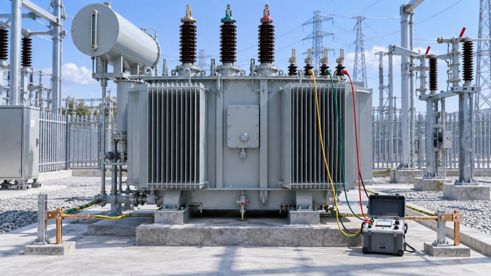
The first practical action is to stop treating the result as a maintenance formality. Keep the transformer isolated, apply the site’s lockout and grounding procedures, and make sure stored capacitive charge has been safely discharged after testing. Insulation systems can retain charge, particularly on larger windings and cable-connected equipment. The test may be complete, but the work is not safe until discharge and verification are complete.
Before opening a tank, ordering oil treatment, or declaring a winding failure, verify the test conditions. Confirm that all external connections that could distort the reading were removed or accounted for. Surge arresters, potential transformers, cable terminations, connected switchgear, electronic monitoring devices, and contaminated bushing surfaces can all affect measurements. A common field mistake is testing a transformer and an attached circuit together, then assuming the transformer itself is defective.
Record exactly what was tested: high-voltage winding to ground, low-voltage winding to ground, high voltage to low voltage, or another configuration. Note the ambient temperature, weather conditions, transformer oil temperature where relevant, test instrument used, applied voltage, test duration, and observed values over time. If the test report only says “failed,” it is not yet a diagnostic record; it is a prompt to investigate.
A low reading and an unstable reading are not the same problem
A low but stable insulation-resistance value may suggest moisture, surface leakage, or aged insulation. A reading that continues to collapse during the test can be more concerning, especially if it indicates active leakage or an insulation path developing under voltage. Conversely, a reading that rises gradually may reflect normal dielectric absorption behavior, although it still needs to be judged against the transformer’s condition history and applicable maintenance criteria.
Trend data is often more valuable than one absolute number. A transformer that has shown a steady decline across comparable tests deserves attention even if it has not crossed a site-defined threshold. On the other hand, a single poor result that cannot be repeated after correcting a wet terminal box or disconnected accessory may be a testing issue rather than an internal failure.
Start With the Most Likely External Causes
Field troubleshooting should usually begin outside the tank. It is faster, less invasive, and frequently revealing. Inspect bushings for dirt, salt deposits, carbon tracking, cracked porcelain or polymer housings, oil seepage, and damaged creepage surfaces. In coastal, dusty, or heavily industrial environments, contamination can create a leakage path that produces disappointing insulation readings without immediately proving winding insulation failure.
Terminal boxes and marshalling cabinets deserve similar attention. Condensation, damaged cable glands, insects, loose covers, and aged auxiliary wiring can compromise the test arrangement. If the transformer has been stored, transported, or left de-energized during a humid season, moisture in external compartments is not a minor detail. It can be the entire explanation.
For oil-filled units, inspect obvious signs of compromised sealing: breather condition, conservator issues, gasket leakage, pressure-relief device condition, and evidence of water entry. A saturated desiccant breather does not diagnose the transformer by itself, but it is a useful clue. Moisture is particularly troublesome because it affects both solid insulation and oil, while also accelerating insulation aging over time.
Interpret the Reading in Context, Not Against a Universal Number
There is no single insulation-resistance number that can responsibly classify every transformer as safe or unsafe. Distribution and power transformers differ in size, voltage class, insulation design, age, oil condition, test method, and service environment. Manufacturer guidance, commissioning requirements, internal asset-management rules, and applicable local standards should establish the acceptance basis for the specific equipment.
Temperature correction matters. Insulation resistance changes substantially with temperature, so comparing a cold-weather reading with a previous hot-weather result without correction can lead to the wrong conclusion. Humidity also affects surface leakage, especially on exposed bushings. If a test has been performed after rain, washdown, flooding, or long storage in damp conditions, repeat testing under controlled conditions may be justified after inspection and appropriate drying.
Use Follow-Up Tests to Narrow the Fault, Not to Generate More Paperwork
If the failed result remains after external causes and setup errors have been addressed, the next step is a coordinated diagnostic plan. The appropriate tests depend on transformer type, criticality, symptoms, and available outage time. Common follow-up work can include transformer turns ratio testing, winding resistance measurement, power-factor or dissipation-factor testing, excitation-current testing, frequency-response analysis, bushing assessment, and oil sampling for dielectric strength, moisture, dissolved gases, and other condition indicators.
None of these tests should be treated as a magic answer. Oil results may reveal moisture or thermal and electrical fault signatures, but they must be interpreted in relation to the transformer’s design and operating history. Frequency-response testing can be useful when mechanical winding movement is suspected, yet meaningful comparison often depends on baseline records or phase-to-phase analysis. A winding resistance anomaly may point to a connection or tap-changer issue rather than the insulation system itself.
That is why a good investigation looks for agreement between signals. A low insulation result, wet oil, degraded dielectric test values, and a history of seal leakage form a more coherent story than any one item alone. By contrast, a single poor megohmmeter reading paired with clean, dry, repeatable supporting results may shift attention back to test boundaries or surface conditions.
Choose the Corrective Action Based on Root Cause
Cleaning and drying may be sufficient when the issue is external contamination or condensation. This work needs discipline: restore clearances, inspect for tracking damage, replace compromised seals or gaskets where needed, and retest after the equipment has stabilized. Simply wiping a bushing and accepting the next reading without documenting conditions can hide a recurring environmental problem.
Where moisture has entered the insulation system, the solution may involve oil processing, vacuum treatment, controlled drying, or factory-level intervention, depending on the transformer’s construction and the severity of the condition. Drying a transformer improperly can cause as much trouble as it solves. Excessive thermal stress, inadequate vacuum control, or rushed re-energization can leave moisture in paper insulation or introduce new risks. Follow the manufacturer’s procedure and use a repair facility or specialist with appropriate equipment when internal drying is required.
If diagnostics indicate internal insulation damage, carbonization, winding deformation, or a bushing failure with collateral effects, repair-versus-replace decisions become operational rather than purely technical. Consider the transformer’s role in the network, spare availability, expected repair scope, lead times, and the consequences of another outage. A lightly loaded auxiliary transformer and a critical generator step-up transformer should not be evaluated through the same risk lens.
Avoid the Shortcuts That Create Repeat Failures
The most dangerous shortcut is energizing because “the transformer was running before.” Insulation condition can change during outage, transport, weather exposure, fault events, or maintenance activity. Another common error is accepting a repeat test merely because the number improved. Improvement matters, but the reason for improvement matters more. If a contaminated bushing was cleaned, that explanation is plausible. If no condition changed and the reading moved dramatically, investigate instrument settings, test leads, grounding, and repeatability.
Do not overlook the test instrument either. Verify calibration status, lead integrity, correct voltage selection, and operator procedure. In high-voltage maintenance, poor testing discipline can waste a day; poor diagnosis can waste a transformer.
For organizations managing geographically dispersed assets, the broader lesson is to build usable condition history. GPEGM’s coverage of power equipment, digital-grid development, and energy infrastructure repeatedly points to the same operational reality: asset intelligence is strongest when electrical test records, oil-condition information, environmental exposure, loading history, and maintenance actions can be reviewed together. Digital records do not replace engineering judgment, but they make it much easier to see whether a failed test is an isolated event or part of a developing pattern.
The Decision Before Return to Service
Before energizing, confirm that the failed insulation test has been explained, not merely retaken. The return-to-service decision should reflect documented test conditions, inspection findings, supporting diagnostics, corrective work completed, and the transformer’s duty. Where uncertainty remains on a critical asset, escalation to a qualified transformer engineer or specialist service provider is usually cheaper than learning the answer during an in-service failure.
A failed insulation test is not always a verdict of transformer loss. It is, however, a clear signal to slow down, isolate the cause, and make the next decision on evidence. That approach protects the transformer, the connected grid, and the people expected to work around both.
Related News
- What Should You Do If a Transformer Insulation Test Fails?Oct 01, 2026What happens if a transformer insulation test fails? Learn the critical safety steps, likely causes, diagnostic tests, and repair decisions before return to service.
- How portal transformers protect power equipment from voltage surgesSep 21, 2026Power equipment portal transformers help manage voltage-surge risk through insulation coordination, arrester placement, grounding, and winding design. Explore practical protection insights.
- How to size an indoor dry type transformer for a commercial buildingAug 29, 2026Indoor dry type transformer sizing guide for commercial buildings: calculate demand, assess harmonics, ventilation, voltage, fault duty, and future expansion.
- Dry Type Transformer for Building: Key Sizing and Safety ChecksJul 04, 2026Dry type transformer for building selection made simple: learn key sizing, harmonic, ventilation, and safety checks to improve reliability, compliance, and long-term project value.
Related News
- 00
0000-00
How professional intelligence for engineers reduces design rework - 00
0000-00
When is metal enclosed switchgear the right fit for industrial sites? - 00
0000-00
How to size medium voltage cable systems for industrial loads - 00
0000-00
How smart switchgear condition monitoring detects early faults - 00
0000-00
How industrial infrastructure development can reduce project delivery risk