
Industrial automation components should be replaced when their condition, support status, and operating behavior create more risk than their continued use can justify. A failed component is an obvious trigger, but waiting for visible failure is often the most expensive approach. A drive that trips intermittently, a controller with shrinking spare-part availability, a sensor that drifts outside process tolerance, or a contactor with heat damage may still operate today while creating an increasingly fragile production system.
The replacement decision should be based on evidence from the equipment's duty cycle, environment, maintenance record, control requirements, and consequence of failure. Age matters, especially where capacitors, relays, insulation, fans, batteries, and mechanical interfaces are involved, but calendar age alone does not establish the remaining useful life of a component. A lightly loaded module in a clean, temperature-controlled enclosure can outlast a newer unit exposed to vibration, conductive dust, voltage transients, moisture, and frequent switching.
Replace Components Before Intermittent Faults Become Production Failures
Intermittent behavior is one of the strongest warning signs because it is difficult to diagnose during short inspections and tends to worsen under real operating conditions. A programmable controller may restart only during a voltage dip. A variable frequency drive may fault after several hours at high ambient temperature. A proximity sensor may work during commissioning but miss targets when oil mist accumulates on its sensing face. These faults can be dismissed as isolated events until they interrupt a critical sequence, damage material, or leave equipment in an unsafe state.
Repeated resets are not a repair strategy. If an alarm returns after wiring checks, parameter verification, cleaning, and controlled testing, the issue should be treated as a reliability problem. The pattern matters: faults linked to peak load suggest thermal stress, undersized power conversion, or deteriorating output devices; faults during startup can point to inrush, weak DC bus capacitors, loose terminals, or power-supply limitations; faults that appear after washdown may indicate compromised seals, cable glands, connectors, or enclosure protection.
Trend data is more useful than a single fault code. Record the fault type, time, machine state, input voltage, load condition, enclosure temperature, and corrective action. A component that trips once after an external power disturbance does not automatically require replacement. The same trip recurring under stable supply conditions deserves a different response. Replacement becomes appropriate when troubleshooting no longer produces a durable explanation or when the component's unstable behavior threatens a process that cannot tolerate an unplanned stop.
Service Life Is Shaped by Duty, Heat, and the Installation Environment
Many automation assemblies contain parts that wear or age even when the system appears healthy. Cooling fans accumulate dust, lose bearing quality, and reduce airflow. Electrolytic capacitors in drives and power supplies degrade faster when exposed to sustained heat. Relay contacts erode through repeated switching, particularly when controlling inductive loads. Battery-backed controller memory and real-time clocks can fail without affecting normal operation until a shutdown or maintenance outage reveals the problem.
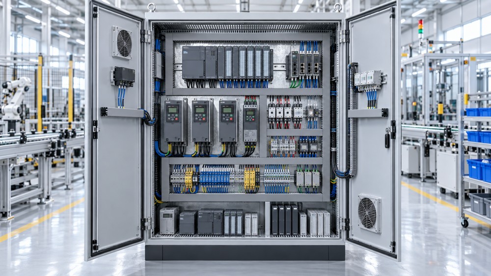
Heat deserves particular attention. High enclosure temperature does not always mean the drive or controller itself is defective. Restricted cabinet airflow, clogged filters, failed fans, overcrowded DIN rails, undersized enclosures, and nearby heat-producing devices can accelerate aging across the entire panel. Replacing one failed drive without correcting its thermal environment can simply restart the same failure cycle. Before selecting a replacement, verify actual cabinet temperature during the highest expected load, not only during an idle inspection.
Electrical conditions matter as much as ambient conditions. Repeated supply imbalance, harmonics, grounding deficiencies, poor shielding, and switching transients can stress sensitive electronics. Long motor cables may create reflected-wave effects at drive outputs; frequent braking may overload a braking circuit; rapid load changes can expose weak power supplies. If the application has changed since the original installation, the component may no longer be correctly sized even though its nameplate rating appears adequate.
Obsolescence Can Justify Replacement Before Hardware Fails
A component can remain electrically functional while becoming operationally obsolete. The practical issue is not whether it still powers up; it is whether a fault can be restored within the required recovery window. When a controller, HMI, remote I/O rack, communication card, servo amplifier, or safety relay is no longer supported, repair time often becomes dependent on uncertain inventory, used equipment, undocumented substitutions, or legacy software that no longer runs reliably on maintained engineering workstations.
Obsolescence should be assessed at the system level. Replacing a single controller can introduce problems if its existing I/O modules, fieldbus network, programming software, operator interface, motion configuration, or safety circuit cannot be retained. Conversely, retaining one unsupported communication card can prevent an otherwise modern control platform from connecting to supervisory monitoring or energy-management systems. The right replacement boundary is the smallest scope that removes the unacceptable dependency without creating unnecessary redesign.
Warning signs include an inability to obtain genuine spare parts through normal channels, repeated reliance on refurbished units with unclear repair history, unavailable firmware or programming tools, and a growing number of workarounds required to modify the machine. A documented migration planned during a scheduled outage is usually safer than an emergency conversion after a legacy unit fails. This is especially true when original drawings, parameter files, source code, or backup images are incomplete.
Distinguish a Component Problem from a Process or Wiring Problem
Replacing hardware without locating the source of the symptom can create costly rework. A fluctuating analog signal may come from sensor drift, but it may also result from a shared reference, poor cable shielding, ground loops, moisture in a junction box, incorrect scaling, or electrical noise from a nearby drive. A drive overcurrent fault may indicate a failing output stage, yet it can also be caused by a damaged motor cable, seized mechanical load, incorrect acceleration settings, or a motor with degraded insulation.
Use comparison and isolation where the machine design permits it. Compare a suspect channel with a known-good channel under equivalent conditions. Inspect terminals for discoloration, looseness, stranded wire escape, and signs of repeated heating. Measure supply voltage at the component terminals while the load is active rather than only at the incoming panel supply. Review parameter changes, replacement history, and recent mechanical modifications. When a defect follows the component after it is moved to an equivalent position, replacement has stronger technical support. When the defect remains at the original position, the investigation should stay focused on the surrounding circuit or process.
This distinction is particularly important for sensors and motion systems. Sensor replacement will not correct a target that moves outside the sensing range because of mechanical wear. Replacing a servo drive will not solve persistent following errors caused by backlash, binding, incorrect load inertia assumptions, or a poorly tuned control loop. The component should be changed when its own measured performance no longer meets the required function, not merely because it is adjacent to the symptom.
Safety-Related Degradation Requires a Lower Threshold
Components involved in emergency stopping, protective interlocks, guard monitoring, overspeed protection, brake control, thermal protection, or controlled shutdown require a more conservative replacement threshold. Evidence of damaged contacts, unreliable feedback, inconsistent reset behavior, unexplained diagnostic states, or altered response timing should not be handled as routine nuisance maintenance.
Replacement also becomes necessary when a modification changes the safety function's assumptions. Adding a higher-inertia load, changing a motor and brake combination, increasing speed, modifying guard geometry, or integrating new control logic can affect the capability of existing safety-related devices. A direct like-for-like replacement may be unsuitable if the machine's operating conditions no longer match the original design basis. The replacement work must preserve verified wiring, device configuration, reset behavior, and functional testing appropriate to the equipment.
Maintenance Cost Should Include Recovery Burden, Not Only Part Price
A low-cost repair can be sensible for a noncritical component with a known failure mode and readily available parts. It becomes less attractive when recurring diagnosis consumes maintenance hours, requires repeated production interruptions, or depends on specialist knowledge that is no longer documented. The true burden includes fault finding, machine cleanup, rejected material, restart checks, emergency freight, configuration recovery, and the risk of a second failure during ramp-up.
Replacement is often justified when the repair history shows a shift from isolated wear items to repeated, unrelated faults. For example, replacing a drive fan is normal preventive maintenance; replacing fans, capacitors, interface boards, and power modules over successive shutdowns may indicate that the entire unit has reached a point where further repair offers poor predictability. The same logic applies to relay panels with widespread contact wear, I/O stations with repeated communication loss, and operator terminals with failing touch layers or display backlights.
Plan the Replacement as a Controlled Change
A replacement project succeeds or fails on details that are easily overlooked during an urgent breakdown. Capture the existing part number, firmware revision, parameter set, network address, wiring terminations, motor data, I/O mapping, and application-specific settings before removing the old unit. Photos are useful for cable routing and physical layout, but they do not replace verified drawings or a structured configuration backup.
Confirm physical compatibility early. A newer device may need a different mounting pattern, deeper enclosure clearance, revised heat dissipation, different connector type, altered control voltage, or a new communication interface. Cable bend radius and connector access can become real installation constraints in crowded panels. For drives and motion equipment, check motor current, voltage class, encoder interface, braking requirements, cable length, output filtering, and control mode rather than selecting solely by rated power.
Commissioning should include more than confirming that the machine starts. Test normal sequences, loss-of-signal behavior, network recovery, power restoration, interlocks, alarms, manual functions, and the highest expected operating load. Verify that scaling, direction, speed limits, acceleration, and fault responses remain correct. Changes to controller scan behavior or communication update timing can affect equipment that appeared unchanged during a basic functional test.
Replacement is most effective when it is treated as a reliability decision supported by operating evidence. Components do not need to fail catastrophically before action is warranted. Stable output, recoverable support, safe behavior, maintainable configuration, and predictable restoration are the conditions worth preserving. When those conditions erode, scheduled replacement becomes a practical form of risk control rather than an avoidable expense.
Related News
- How smart switchgear condition monitoring detects early faultsSep 28, 2026Smart switchgear condition monitoring detects early thermal, insulation, partial discharge, and breaker faults—helping teams prevent outages and plan safer maintenance.
- How to size power equipment for factories without overbuilding capacitySep 26, 2026Power equipment for factories: learn how to size transformers, switchgear, and backup power using real demand data—avoiding excess cost while enabling reliable growth.
- When Should Industrial Automation Components Be Replaced?Sep 29, 2026When should industrial automation components be replaced? Identify warning signs, obsolescence risks, safety concerns, and smart replacement strategies to prevent costly downtime.
- What an intelligence portal for electronics industry should trackSep 18, 2026An intelligence portal for electronics industry tracks technology, demand, supply risks, standards, and competitors—turning complex signals into smarter decisions.
Related News
- 00
0000-00
How to size medium voltage cable systems for industrial loads - 00
0000-00
How smart switchgear condition monitoring detects early faults - 00
0000-00
How industrial infrastructure development can reduce project delivery risk - 00
0000-00
How to size power equipment for factories without overbuilding capacity - 00
0000-00
How efficiency evolution in automation is reshaping factory energy use