
For sensitive equipment, rectifier ripple should be specified at the load terminals, across the full operating range, rather than accepted from a single supply datasheet value. A practical starting point is to keep low-frequency ripple below the voltage tolerance that would affect the load’s analogue reference, control threshold, communication margin, or stored-data integrity. Precision measurement circuits often need ripple in the millivolt range; ordinary digital control electronics may tolerate substantially more if local regulation and decoupling are sound. The acceptable level is therefore a system requirement, not a universal percentage.
Ripple is the residual alternating component superimposed on a rectified DC output. It is commonly stated as peak-to-peak voltage, RMS voltage, or a percentage of nominal DC voltage. Those descriptions are related but are not interchangeable. A supply described as having “1% ripple” is incomplete unless the nominal voltage, measurement bandwidth, load current, rectifier configuration, and test point are also known.
Set the limit from the disturbance the load can tolerate
Start with the load rather than the rectifier. A 24 V control circuit with a wide input range can remain functional through a relatively large ripple excursion, while a 5 V analogue front end powered from the same cabinet may show measurement drift long before the control circuit resets. If the DC rail supplies several functions, each branch needs separate consideration. The strictest branch often determines the upstream requirement unless local filtering or point-of-load regulation isolates it.
For many industrial control, relay, solenoid, and general digital loads, a low single-digit percentage of nominal DC voltage is a reasonable design target when the supply voltage margin remains adequate. That target becomes too loose for sensor excitation, data acquisition, low-level signal conditioning, timing references, RF circuits, audio paths, and precision motion feedback. In these applications, specify an absolute ripple value at the sensitive rail, often in millivolts peak-to-peak over a defined bandwidth, and include permissible transient deviation separately.
A useful distinction is between functional tolerance and performance tolerance. Functional tolerance asks whether the equipment remains powered and avoids reset, fault, or loss of communication. Performance tolerance asks whether readings, position feedback, noise floor, timing, or output quality remain within the intended accuracy. A power rail can pass a functional test while still degrading the process it supports.
Do not treat all ripple as the same waveform
The usual ripple from a mains-frequency bridge rectifier has a predictable low-frequency component. With full-wave rectification, the dominant frequency is twice the AC line frequency. Its amplitude rises as load current increases, capacitance falls, input voltage drops, or the capacitor’s equivalent series resistance increases. A simple capacitor-input supply may show a sawtooth-like waveform with narrow charging peaks and a deeper discharge interval between them.
Switching converters introduce a different problem. Their output may have high-frequency ripple, ringing, burst-mode behavior at light load, and sharp current pulses. A modest RMS figure can hide a high peak-to-peak spike that matters to a comparator or analogue-to-digital converter. Conversely, a visible high-frequency waveform may have little effect on a slow coil or a well-filtered downstream regulator. Frequency content therefore matters as much as amplitude.
Ripple can also be confused with noise that is not generated by the rectifier itself. Common sources include inverter output coupling, switching contactors, motor cable capacitance, poor bonding, shared return conductors, ground loops, and input voltage disturbances. Adding bulk capacitance will reduce low-frequency discharge ripple but may do little for a fast spike coupled into a signal reference. Diagnosing the waveform before changing components prevents expensive but ineffective filtering.
Define the measurement before comparing specifications
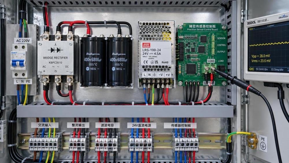
A ripple requirement without a measurement method invites disagreement. A probe connected with a long ground lead can display loop-picked-up noise that is absent at the load. A meter may average away peaks that an oscilloscope reveals. A supply tested at no load may appear clean, then develop deep ripple valleys when a motor brake or valve bank is energized.
Measure at the actual load connection with the expected cable arrangement. Use a short probe ground spring or a suitably terminated coaxial connection for high-frequency work. Record the DC level, peak-to-peak ripple, RMS ripple where relevant, dominant frequency, bandwidth limit, load current, and operating state. The observation should include cold start, steady load, minimum and maximum input voltage, light-load operation, and fast load changes if those occur in service.
Bandwidth must be stated. A 20 MHz oscilloscope limit often gives a useful comparison for general DC supplies, but it is not automatically the right limit for every installation. A lower bandwidth may be appropriate when evaluating a slow analogue process; a wider bandwidth is needed when assessing fast digital logic, RF circuits, or electromagnetic interference. The objective is to include disturbance frequencies that can reach the susceptible circuit while excluding measurement artifacts.
Peak-to-peak ripple is especially useful for dropout risk because it shows the lowest rail voltage. RMS ripple is more useful when estimating heating or noise energy. Neither measurement identifies short transient dips automatically. A separate capture of load-step response is needed where electronic loads, solenoids, contactors, or drive control stages produce abrupt current demand.
Calculate the first estimate, then verify it under load
For a full-wave rectifier followed by a reservoir capacitor, a first-order estimate of capacitor discharge ripple is:
Vripple(pp) approximately equals Iload divided by fripple multiplied by C.
Here, Iload is DC load current, fripple is the rectified ripple frequency, and C is reservoir capacitance. The expression is useful for sizing and sanity checking, but it assumes a relatively steady load and does not account fully for transformer regulation, diode drop, capacitor ESR, line impedance, mains distortion, or pulsed current draw.
The minimum DC voltage matters more than the average output. A nominal 24 V rail may appear satisfactory at its average value but fall below an input module’s hold-up threshold near the bottom of each ripple cycle. Cable resistance, connector loss, fuse resistance, and shared return current can deepen that valley at the remote device. Specify the lowest voltage at the sensitive terminals during the expected operating condition, not merely at the rectifier output.
Capacitor ESR adds a step-like voltage component whenever current changes. Ageing, elevated cabinet temperature, and insufficient ripple-current rating raise ESR over time. A capacitor selected only by capacitance can meet a bench calculation yet produce excessive ripple in the installed assembly. Ripple-current capability, temperature rating, expected service life, mounting conditions, and permissible impedance at the relevant frequency all belong in the component review.
Choose the right suppression method for the disturbance
Bulk electrolytic capacitance is effective against low-frequency rectifier ripple because it supplies charge between mains peaks. It should be placed close enough to the rectifier and load path to avoid creating a long, inductive loop. Large capacitance also increases inrush current and rectifier charging current, which may require soft-start design, a suitable bridge rating, transformer margin, and fuse coordination.
An LC or pi filter can attenuate ripple more strongly, but its behavior must be checked with load variation. An inductor reduces pulsating current, while capacitors on either side provide energy storage and shunt AC content. Poor damping can create resonance, causing ringing or an unstable response when downstream converters draw pulsed current. Capacitor ESR sometimes provides enough damping; in other cases, a deliberate damping network is necessary.
A linear regulator after the rectifier offers strong rejection when sufficient voltage headroom remains at the lowest input point. Its published ripple rejection is frequency-dependent, and it falls away as the input-to-output differential approaches dropout. A regulator cannot remove ripple after its input dips below the voltage needed to regulate. Thermal dissipation also rises with the voltage drop and load current, so a design with generous headroom at high line must still be checked for heat.
A switching DC-DC stage can regulate a fluctuating upstream rail efficiently, yet it adds its own switching noise. Sensitive branches often benefit from a two-stage arrangement: a robust bulk DC bus for power loads, followed by a local converter or low-noise regulator for instrumentation. Ferrite beads and small ceramic capacitors are effective for high-frequency isolation near an integrated circuit, but they are not substitutes for reservoir energy where the problem is low-frequency voltage sag.
Grounding and wiring can invalidate a good supply specification
Ripple measured between a local positive rail and its local return may be acceptable while the equipment still misbehaves because the signal reference is moving. Shared return conductors are a common cause. Motor current or coil current flowing through the same return path as an analogue sensor produces a voltage drop that appears directly as measurement error. The supply itself may be within specification, but the reference seen by the sensor is not.
Separate high-current returns from low-level signal returns until a controlled connection point. Keep rectifier charging loops short and physically away from input amplifiers, encoder wiring, and communication pairs. Shield termination should follow the interface and installation requirements; a shield connected indiscriminately at multiple points can introduce circulating current rather than remove noise. Bonding, cable routing, and enclosure continuity deserve examination before the ripple limit is tightened unnecessarily.
Long DC runs also create voltage drop and inductance. A remote device can see a deeper ripple waveform than the panel supply output, especially where loads share a cable trunk. Local bulk capacitance may reduce the immediate dip, but it should be sized with fault behavior in mind. Stored energy can alter disconnect time, arc energy, and inrush conditions. Protection devices and conductors must be evaluated with the added capacitance in place.
Separate normal ripple from fault signatures
A gradual increase in low-frequency ripple at a stable load often points to reduced effective capacitance or rising ESR. A waveform that becomes asymmetric can indicate a rectifier diode problem, transformer imbalance, or a poor connection in the AC path. Repetitive narrow spikes synchronized with switching activity suggest coupling from another converter or drive. Random bursts are more consistent with contact arcing, loose terminals, intermittent grounding, or external interference.
Trend the waveform at a fixed operating point when equipment reliability matters. A single RMS measurement is rarely enough to reveal deterioration. Capture peak-to-peak voltage, minimum rail voltage, temperature near the capacitor bank, load current, and the condition of nearby switching equipment. Comparing like-for-like records makes it easier to distinguish a supply ageing issue from a changed load profile.
Write a requirement that can be built and tested
A usable ripple requirement names the nominal output voltage, allowable minimum and maximum voltage, permissible peak-to-peak ripple, relevant frequency range, measurement bandwidth, load range, input range, and measurement location. It should also state whether short load-step deviation is included or limited separately. For a sensitive rail, include any maximum noise level within the signal band and clarify whether the reference return is measured locally or at a remote point.
For example, a requirement may distinguish between low-frequency ripple at the rectifier output, high-frequency noise after a switching regulator, and voltage deviation at a remote instrument during a load step. Those are different phenomena with different remedies. Combining them into one broad “ripple” figure makes acceptance testing ambiguous and can conceal the condition that actually disrupts the equipment.
The acceptable rectifier ripple level is the level that leaves adequate voltage margin and preserves the required electrical performance at the most sensitive connection point. Establish that limit from the load’s real susceptibility, measure it with a defined method, and address the frequency and path of the disturbance rather than adding filtering by habit.
Related News
- What an intelligence portal for electronics industry should trackSep 18, 2026An intelligence portal for electronics industry tracks technology, demand, supply risks, standards, and competitors—turning complex signals into smarter decisions.
- How electrical engineering for factories prevents costly downtimeSep 16, 2026Electrical engineering for factories helps prevent costly downtime through selective protection, resilient control power, and smarter monitoring. Learn practical strategies now.
- Which inverter technology standards apply to grid-connected systems?Sep 14, 2026Inverter technology standards explained: explore safety, anti-islanding, grid codes, power quality, and certification checks for reliable grid-connected systems.
- What determines the required switchgear fault withstand rating?Sep 13, 2026Switchgear fault withstand rating explained: learn how fault current, clearing time, network configuration, and future expansion shape safe, cost-effective selection.
Related News
- 00
0000-00
How to verify suppliers listed in a power system supplier directory - 00
0000-00
What an intelligence portal for electronics industry should track - 00
0000-00
What to verify before choosing an energy storage system supplier - 00
0000-00
How electrical engineering for factories prevents costly downtime - 00
0000-00
When does a smart grid for buildings reduce peak demand charges?