
Does a DC Motor Need a Separate Controller?
Does a DC motor need a separate controller? The answer depends on the motor type and what your application demands. A brushed DC motor can run directly from a suitable DC supply, while a brushless DC motor requires electronic commutation, provided by integrated electronics or an external controller. For equipment designers and industrial buyers, the real question is whether speed regulation, reversing, current limiting, or controlled starting is essential.
That distinction matters when specifying conveyors, pumps, fans, actuators, and battery-powered equipment. A motor that turns successfully on a workbench may still overheat, trip its supply, or stop unpredictably under production conditions. The right decision starts with the load and operating cycle—not simply the voltage printed on the motor label.
A motor needs commutation, but not always a separate box
In a brushed DC motor, brushes and a commutator switch current between armature windings mechanically. For a permanent-magnet brushed motor, applying an appropriate DC voltage across its terminals is generally enough to produce rotation. An external controller adds capabilities; it does not provide the basic commutation needed to turn the shaft.
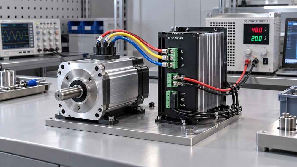
A brushless DC motor, or BLDC motor, works differently. Semiconductor switches must energize its phases in the correct sequence according to rotor position. This requires drive electronics, whether they sit inside the motor housing, on a nearby circuit board, or in a separate cabinet.
Consequently, a two-wire brushless fan may run when connected to DC because its controller is already built in. A bare three-phase BLDC motor cannot be connected directly to a battery and expected to run continuously. The power source supplies energy; the controller performs commutation.
Industrial wound-field DC motors need additional care. Shunt, series, and separately excited designs have different connection and operating requirements. Field-loss protection or restrictions on unloaded operation may apply. The simple “connect two wires” advice should not be extended to these machines without checking their documentation.
When direct connection is a reasonable choice
Direct operation can make sense for a brushed permanent-magnet motor performing a straightforward, one-direction task. The application must tolerate its natural speed variation, the supply must handle starting demand, and the mechanical system must withstand an abrupt start.
Consider a small auxiliary blower that only needs to switch on and off. If its motor is approved for direct operation, startup is acceptable, and airflow remains adequate across expected supply and load conditions, a dedicated speed controller may add little value. Proper switching, wiring, and protection are still required.
The main limitation is that a fixed supply voltage does not guarantee fixed speed. In a brushed motor, speed reflects both applied voltage and the voltage drop associated with armature current. As load torque increases, current rises and speed generally falls. Battery discharge and cable voltage drop can introduce further variation.
Direct connection also exposes the supply to startup current. At standstill, there is no rotational back electromotive force opposing the applied voltage. Current is initially limited mainly by circuit resistance and inductance, unless the supply or another device limits it. Rated running current is therefore not a sufficient basis for selecting the supply.
No controller does not mean no protection. A fuse or circuit breaker, suitable disconnect, and correctly rated switching device may still be necessary. Inductive switching transients need an appropriate suppression path. A simple flyback diode can suit some one-direction circuits, but it is not a universal solution for reversing or fast-braking systems.
What changes the decision in industrial service?
Speed must remain stable as the load changes
A conveyor carrying uneven loads may need more than an adjustable voltage. Open-loop pulse-width modulation, or PWM, changes the effective voltage delivered to the motor efficiently, but a fixed duty cycle does not hold speed constant against every disturbance.
Where process consistency depends on shaft speed, closed-loop control is often appropriate. An encoder, tachometer, or suitable estimation method provides feedback, allowing the drive to correct deviations. Specify the required regulation across the working speed and torque range rather than asking only for “variable speed.”
Starting torque and acceleration need limits
Gearboxes, couplings, belts, and transported materials may not tolerate full-voltage starting. A controller can ramp acceleration and limit current, reducing electrical and mechanical stress. However, reducing current also reduces available torque in a permanent-magnet DC motor. Set the limit too low and a loaded mechanism may never accelerate.
This is particularly relevant to high-friction actuators and conveyors that start under load. The drive must support the required peak current for the actual acceleration period, not merely advertise a brief peak rating under unspecified cooling conditions.
Reversing and stopping are part of the process
A brushed permanent-magnet motor reverses when its terminal polarity is reversed. Implementing that repeatedly under load requires suitable switching and sequencing. An H-bridge drive provides electronic reversal, but not every H-bridge offers controlled braking or regeneration.
Stopping deserves its own specification. Coasting, dynamic braking, and regenerative braking produce different stopping behavior and energy flows. A lowering load or rapidly decelerating flywheel can return energy to the DC bus. If the supply cannot absorb it, bus voltage can rise beyond equipment limits. The system may need a compatible regenerative supply, a battery capable of accepting charge, or a braking circuit.
A normal stop command is also not automatically a safety function. Machinery requiring emergency stopping, safe torque removal, or load holding needs an appropriate risk assessment and safety architecture. Electronic braking should not be assumed to replace a mechanical holding brake.
Integrated electronics or an external drive?
Once electronic control is required, a separate controller is still not inevitable. Integrated motor-drive assemblies can reduce external wiring and eliminate some motor-to-drive compatibility questions. They can be practical where the motion requirements are defined and installation space is tight.
The trade-off is serviceability and heat management. Electronics mounted on the motor share its local thermal environment. If a drive component fails, replacement options depend on the assembly design and supplier support. Access for configuration and diagnostics also deserves attention before installation.
An external controller allows the electronics to be located in a more suitable environment and may offer broader feedback, communications, and braking options. It also introduces cabling, enclosure, electromagnetic compatibility, and commissioning work. Longer motor cables can increase emissions and switching-related electrical stress, so installation limits should follow the drive manufacturer’s guidance.
Neither architecture is automatically more efficient or economical. Compare the complete installed system, including cooling, connectors, enclosure space, commissioning, spare parts, and downtime—not just the motor and controller prices.
Match the controller to the operating envelope
A voltage match is only the beginning. Before approving a drive, put the following requirements in the same specification:
- Motor construction: brushed permanent-magnet, wound-field, or BLDC, including winding connections and any field supply requirements.
- Supply envelope: nominal, minimum, and maximum voltage, available current, and the supply’s behavior during overload or regeneration.
- Load cycle: continuous torque, breakaway torque, acceleration time, reversals, and expected stall conditions.
- Drive ratings: continuous output current at the actual ambient temperature, plus peak current and its permitted duration.
- Feedback compatibility: Hall sensors, encoders, signal voltage levels, connector pinouts, and required low-speed performance.
- Installation conditions: enclosure, cooling, contamination, cable length, grounding, and electromagnetic compatibility requirements.
For BLDC systems, sensorless operation needs particular scrutiny at startup and very low speed. Some methods rely on back-EMF information that becomes weak at low rotational speed. Other methods can improve this behavior, but reliable loaded starting should be confirmed for the actual motor-controller combination.
PWM operation also affects thermal performance. Low-speed, high-torque duty can produce substantial winding heat while a shaft-mounted fan provides little cooling. A controller that maintains torque does not remove the motor’s thermal limits. Check the permitted duty cycle and whether separate cooling is needed.
Test the difficult operating points before committing
A useful acceptance test goes beyond unloaded rotation. Check cold and warm starts, maximum expected load, minimum supply voltage, repeated reversals, and the longest demanding duty cycle. Confirm what happens after a jam or power interruption, including whether the equipment restarts automatically.
Measure current, bus voltage, speed, and relevant temperatures during these tests. For regenerative applications, observe bus voltage during deceleration and overhauling loads. For precision motion, verify speed or position behavior at the lowest required operating point. These checks reveal integration problems that headline power ratings cannot.
This system-level approach aligns with the focus of the Global Power & Electrical Grid Matrix (GPEGM): connecting motion-drive engineering with power electronics, energy distribution, and industrial investment decisions. For buyers evaluating drive technology, the useful comparison is not simply brushed versus brushless. It is how each motor, controller, and supply combination meets the required duty with manageable losses, maintenance, and integration risk.
The practical answer is therefore specific: a suitable brushed DC motor may run without a separate controller; a BLDC motor needs electronic commutation, but that electronics may already be integrated. Choose external control when the process requires capabilities the existing arrangement cannot reliably provide. Before ordering, confirm the load cycle, starting current, feedback needs, stopping method, and supply compatibility together.
Related News
- Does a DC Motor Need a Separate Controller?Nov 02, 2026Does a DC motor need a separate controller? Compare brushed and BLDC requirements, explore control options, and learn how to choose the right setup for reliable performance.
- How Do I Compare Electric Motor Lifetime Costs?Oct 30, 2026How do I compare electric motor lifetime costs? Explore energy, maintenance, downtime, and payback with a worked example to make smarter motor purchasing decisions.
- How to size medium voltage industrial motors for high-inertia loadsOct 24, 2026Size medium voltage industrial motors for high-inertia loads with confidence. Learn how to check torque, acceleration, thermal limits and starting methods to avoid costly failures.
- Can Motor Drives Be Retrofitted to Existing AC Motors?Sep 27, 2026Can motor drives be retrofitted to existing AC motors? Learn key VFD compatibility checks, installation risks, energy-saving benefits, and retrofit best practices.
Related News
- 00
0000-00
How to assess a smart grid device manufacturer's interoperability - 00
0000-00
How to size a containerized energy storage system for peak shaving - 00
0000-00
How to use a global power matrix for procurement negotiations - 00
0000-00
Can an electrical grid platform integrate with legacy SCADA systems? - 00
0000-00
Can an electrical grid intelligence dashboard detect outages?