
A production line that has run for years at a fixed motor speed can become difficult to control when product flow, pressure, temperature, or throughput changes. Operators may compensate with throttling valves, dampers, mechanical bypasses, or frequent start-stop cycles. Those methods can waste energy and increase wear, especially on pumps, fans, conveyors, mixers, and compressors.
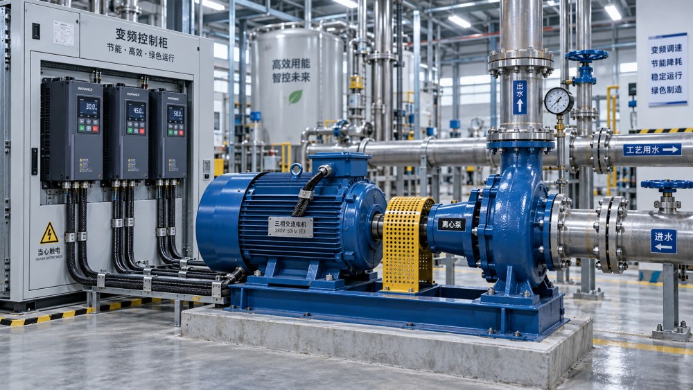
Can motor drives be retrofitted to existing AC motors? In many cases, yes. A variable-frequency drive (VFD), also called an AC drive or inverter, can be added to an existing AC motor without replacing the motor itself. The retrofit is not automatic, however. Motor type, insulation condition, load behavior, cable length, voltage, cooling, and the required speed range all need to be checked before the drive is selected and commissioned.
Start with the motor: not every AC motor has the same retrofit path
The most straightforward candidates are three-phase squirrel-cage induction motors. These motors are widely used in industrial equipment and can usually operate with a properly sized VFD when their electrical and mechanical condition is sound. A drive controls motor speed by changing the frequency and voltage supplied to the motor, allowing the driven machine to match actual process demand instead of operating continuously at full speed.
Older motors can also be suitable, but age alone should not be treated as proof of compatibility. A motor that performs acceptably on direct-on-line power may reveal insulation weaknesses when exposed to the fast switching voltage pulses produced by a modern drive. This is particularly relevant where the motor has been rewound, stored in a damp environment, subjected to repeated overloads, or operated near high ambient temperatures.
Single-phase motors, shaded-pole motors, capacitor-start motors, and motors with internal centrifugal switches require more caution. Most general-purpose VFDs are designed for three-phase induction motors. Retrofitting a drive to a single-phase motor is often impractical or unreliable; replacing the motor with a three-phase motor and adding a drive is frequently the more dependable route.
Motors with special brake assemblies, integrated electronics, permanent-magnet designs, or unusual feedback systems may also require a drive specifically matched to that motor technology. The nameplate is the starting point, not the final answer.
What to collect before choosing a drive
A retrofit decision becomes much easier when the existing equipment is documented before anyone compares drive catalog ratings. The motor nameplate should provide rated voltage, full-load current, frequency, output power, speed, service factor where applicable, and wiring configuration. Confirm whether the facility supply matches the motor connection arrangement. A dual-voltage motor, for example, may need different terminal links depending on whether it is connected to the drive at the lower or higher rated voltage.
The driven load matters just as much as the motor. A centrifugal pump or fan generally requires less torque as speed falls, making it a favorable variable-speed application. Conveyors, positive-displacement pumps, crushers, hoists, and extruders may demand substantial torque at low speed or during acceleration. A drive sized only from motor kilowatts can be inadequate if the process has high breakaway torque, rapid acceleration requirements, or repeated heavy starts.
- Motor data: rated current, voltage, frequency, speed, insulation class, duty rating, and connection method.
- Load data: starting torque, running torque, inertia, load variation, required minimum and maximum speed, and direction changes.
- Supply data: incoming voltage, available fault current, grounding arrangement, and whether the site has known power-quality concerns.
- Installation data: motor cable length, cable routing, enclosure space, ambient temperature, dust, moisture, vibration, and cooling conditions.
- Control needs: local speed control, remote start-stop, pressure or flow feedback, network communication, safety interlocks, and emergency-stop architecture.
It is also useful to identify why speed control is being added. Energy reduction, gentler starting, improved process stability, reduced mechanical shock, and better matching of output to demand are valid objectives, but they lead to different commissioning priorities. A pump retrofit focused on pressure control is configured differently from a conveyor retrofit intended to prevent product surges.
The insulation and cable issue that can change a “simple” retrofit
VFD output is not the same as a smooth utility sine wave. The drive produces a pulse-width-modulated waveform with rapid voltage transitions. At the motor terminals, reflected-wave effects can increase peak voltage, particularly when the motor cable is long. The risk rises with higher system voltage, long leads, poor cable practices, and older windings not designed for inverter duty.
This does not mean an existing motor must always be replaced. It means the motor-drive-cable combination must be assessed. A motor insulation resistance test may reveal obvious moisture or insulation deterioration, while a more complete evaluation can include winding condition and the motor’s service history. Testing should be carried out using methods appropriate to the motor and site procedures; indiscriminate high-voltage testing on an aging machine can create its own problems.
Where cable length or motor condition creates concern, the mitigation may include an output reactor, a dv/dt filter, a sine-wave filter, inverter-rated cable, or a combination of these measures. The correct choice depends on the drive output, cable route, motor voltage rating, and manufacturer limits. Output filtering is not merely an accessory decision: it can affect motor terminal stress, audible noise, leakage current, and the usable cable length.
Grounding is part of performance, not just compliance
A drive retrofit introduces high-frequency currents that can behave differently from ordinary line-frequency fault current. Poor bonding between the drive enclosure, motor frame, cable shield, and equipment structure can contribute to electromagnetic interference, nuisance trips, sensor instability, and premature bearing damage in some applications.
Use a low-impedance protective earth path, follow the drive manufacturer’s shield termination requirements, and keep motor output cables separated from sensitive analog, encoder, and communication wiring where practical. Long pigtail shield connections are often less effective at high frequency than proper 360-degree terminations. In installations with precision feedback devices or nearby instrumentation, cable routing and grounding should be reviewed before commissioning rather than after unexplained signal problems appear.
Low-speed operation can overheat a motor that looks lightly loaded
A motor’s shaft-mounted cooling fan turns more slowly when the VFD reduces motor speed. At the same time, some loads still require high torque. This combination can create a thermal problem: the motor may be producing significant torque while receiving much less self-cooling than it had at rated speed.
This issue is easy to miss on a conveyor, mixer, or positive-displacement pump. The process may appear to run normally, but the winding temperature can rise over extended low-speed duty. A standard motor may need a restricted low-speed torque range, reduced load, a separately powered cooling blower, thermal sensors, or replacement with an inverter-duty motor designed for the required operating envelope.
By contrast, fan and pump loads often become easier for the motor as speed is reduced. Their torque demand typically falls with speed, although the actual system curve, static head, fluid characteristics, and control method still need to be considered. Do not assume that every pump is a simple variable-torque load: a positive-displacement pump behaves very differently from a centrifugal pump.
Mechanical limits do not disappear when speed becomes adjustable
A drive can command speeds above the motor’s base speed, but that does not make overspeed safe. Bearings, rotors, couplings, fans, gearboxes, pump impellers, belts, and the driven machine all have mechanical limits. Above-base-speed operation usually enters a field-weakening region where available motor torque declines, so a higher speed command may not deliver the expected load capability.
Minimum speed also has limits. Some pumps need minimum flow to avoid overheating or internal recirculation. Some gearboxes are poorly lubricated at very low input speed. Certain mixers lose process effectiveness below a threshold, while belt conveyors can develop tracking or product-handling problems. A practical retrofit defines a permitted speed window based on the entire machine, not only the motor.
Resonance should be considered during ramp-up and ramp-down. A motor and driven system may pass through vibration-sensitive frequencies that were never encountered during fixed-speed operation. Drives can commonly be programmed with skip-frequency bands so that the system moves through those ranges rather than operating there continuously. This should be based on observed mechanical behavior and engineering review, not arbitrary parameter choices.
Select the drive by current, overload duty, and environment
Drive selection often fails when nominal motor power is treated as the only rating. The drive’s continuous output current must meet or exceed the motor’s required current for the intended duty. Its overload capability must also suit the application. A fan may need a variable-torque rated drive, while a loaded conveyor or process machine may need constant-torque duty and greater short-term overload capacity.
Derating can materially change the available output. High ambient temperature, altitude, high switching frequency, restricted airflow, enclosure type, and side-by-side mounting may reduce the drive’s usable rating. An enclosure that protects electronics from dust or washdown conditions can also retain heat if ventilation is poorly designed. The panel should allow access for maintenance while keeping power and control wiring arranged according to installation guidance.
Input-side components deserve the same attention. Depending on the installation, the retrofit may require a disconnecting means, branch-circuit protection, line reactor, harmonic mitigation equipment, surge protection, and appropriately rated contactors. A contactor should not normally be used to repeatedly start and stop the motor on the drive output; use the drive’s control inputs or communication commands unless the equipment design specifically requires another method.
A commissioning sequence that avoids avoidable faults
Once the electrical and mechanical checks are complete, commissioning should begin with conservative settings. Verify motor wiring, protective earth continuity, rotation direction, control circuit logic, and the condition of all guards and interlocks. Enter the motor nameplate values accurately. Many drives offer a static or rotating motor identification routine; using the appropriate routine can improve torque control and current regulation, but it must only be performed when the machine can safely rotate and the load conditions permit it.
- Run the motor uncoupled where practical, or at a low safe speed with the driven equipment prepared for operation.
- Confirm correct rotation before allowing a pump, fan, conveyor, or other machine to reach normal process speed.
- Set acceleration and deceleration times based on load inertia, process constraints, and the drive’s ability to manage regenerative energy.
- Establish minimum and maximum frequency limits from mechanical and process requirements.
- Observe motor current, drive temperature, vibration, noise, and process response across the intended speed range.
- Test fault response, permissives, local/remote control transfer, and restart behavior after power interruption.
Deceleration is frequently underestimated. A high-inertia fan, centrifuge, conveyor, or rotating machine can return energy to the drive during a fast stop. If the drive cannot absorb or manage that energy, it may trip on DC bus overvoltage. Extending the deceleration ramp may solve the issue, but where a controlled rapid stop is required, a braking resistor, regenerative arrangement, or application-specific braking method may be necessary.
When replacement is the better decision
Retrofitting is not always the lowest-risk choice. Replacement may be preferable when the existing motor has damaged insulation, recurring bearing problems, insufficient thermal capacity, unsuitable voltage, unreliable rewinding history, or a duty cycle that demands sustained low-speed torque beyond its cooling capability. The same applies when a single-phase motor would need an awkward conversion or when the machine requires feedback and dynamic performance the existing motor cannot support.
A motor replacement can also simplify the installation where the expected operating range is broad and continuous. An inverter-duty motor with suitable insulation, thermal protection, and mechanical rating may provide a clearer operating boundary than trying to preserve a marginal legacy unit. The decision should compare downtime, wiring changes, filters, cooling additions, mechanical modifications, and future maintenance—not only the purchase price of the motor.
Questions that often arise during an AC motor drive retrofit
Will a VFD reduce energy use on every motor?
No. Energy savings are most likely when speed can be reduced while still meeting process demand, especially on centrifugal fans and pumps. A constant-torque machine operating at nearly the same speed and load may gain control benefits without delivering the same energy reduction.
Can one drive operate several existing motors?
It can be possible where all motors run together at the same speed and the drive is sized for their combined current. Each motor requires suitable overload and thermal protection, and individual control is limited. Separate drives are generally more flexible when motors need independent starting, stopping, or speed adjustment.
Should the motor remain connected to a bypass starter?
A bypass can be used in some designs to allow direct-on-line operation during drive maintenance, but the switching arrangement must prevent the motor from being connected to the drive output and line supply at the same time. Bypass systems need properly interlocked power components and a clear operating procedure.
Related News
- Can Motor Drives Be Retrofitted to Existing AC Motors?Sep 27, 2026Can motor drives be retrofitted to existing AC motors? Learn key VFD compatibility checks, installation risks, energy-saving benefits, and retrofit best practices.
- Can One Motor Controller Support Different Motor Loads?Sep 22, 2026Can one motor controller support different motor loads? Explore compatibility factors, current limits, protection settings, and practical tips for safer, more efficient drive reuse.
- Is a Premium-Efficiency Motor Worth the Higher Cost?Sep 12, 2026Is a premium-efficiency motor worth the extra cost? Calculate payback, energy savings, lifecycle value, and key selection factors for smarter investments.
- Why Does a DC Motor Overheat Under Variable Load?Sep 15, 2026Why does a DC motor overheat under variable load? Discover how current spikes, low-speed cooling, mechanical drag, and drive settings cause heat—and how to fix it.
Related News
- 00
0000-00
How industrial infrastructure development can reduce project delivery risk - 00
0000-00
How to size power equipment for factories without overbuilding capacity - 00
0000-00
How efficiency evolution in automation is reshaping factory energy use - 00
0000-00
When market scanning services are worth the investment - 00
0000-00
Which international infrastructure projects are reshaping Southeast Asia?