
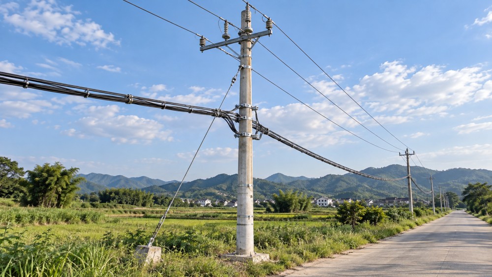
A leaning pole, cracked concrete, or decay at ground level can signal serious risks on 11 kV and 415 V overhead networks. For after-sales maintenance teams, the challenge is deciding whether a defect needs monitoring, specialist assessment, or immediate action before anyone approaches the structure.
Effective 11kv/415 overhead transmission lines maintenance starts with that decision. Although this search term is common, these voltage levels generally belong to distribution networks rather than transmission systems. Pole inspection must consider the complete support arrangement: the pole, foundation, stays, crossarms, attachments, and loads imposed by conductors and equipment.
This guide explains how to assess timber, concrete, and steel poles, recognize defects that visual checks cannot resolve, and turn findings into defensible maintenance decisions. All work must follow the asset owner’s procedures, local electrical safety rules, and approved inspection methods.
Before approaching: decide whether the site is safe to inspect
A pole that appears accessible may still present electrical or collapse hazards. A damaged conductor, defective insulator, or earthing fault can energize steelwork, stays, or nearby ground. A weakened pole may fail when disturbed, even if it has remained standing for years.
Begin with a stand-off observation from a safe position. Look for broken or unusually low conductors, active arcing, smoke, severe lean, displaced foundations, fallen branches, and hanging equipment. Keep people and vehicles outside the potentially affected area and notify the network control or emergency contact when immediate danger is suspected.
- Confirm the circuit and asset identity. Check the pole number, nominal voltage, circuit arrangement, and any shared telecommunications or distribution equipment.
- Review available records. Previous defects, pole material, installation details, repairs, and recent storms help explain what you see.
- Establish the work boundary. Use utility-defined approach distances and controls appropriate to the voltage, activity, personnel, and equipment.
- Separate observation from intervention. Touching, excavating, probing, drilling, climbing, or operating near a pole requires the relevant authorization and risk controls.
Do not climb or load a suspect pole to investigate its condition. Where hands-on work requires isolation, the authorized process must address all possible supplies, including backfeed, and include verification and earthing where required. An open switch alone is not proof that equipment is safe.
Read the whole structure—not just the visible damage
Start with the pole’s surroundings, then follow the load path from the ground to the conductors. This avoids a common mistake: recording a surface defect while missing the movement or loading that caused it.
Ground, foundation, and alignment
Look for erosion, scour, washout, standing water, slope movement, vehicle impact, and recent excavation. Check whether soil has separated from the pole or whether a foundation has cracked or shifted. Roadworks and drainage changes can undermine a previously stable installation without leaving obvious damage higher up.
Assess lean from more than one safe viewpoint. A photograph from a single angle can conceal movement or exaggerate it through perspective. Where approved, use repeatable survey measurements and compare them with earlier records. Do not assume a lean is acceptable because neighboring poles have a similar appearance; foundation rotation, pole bending, and an intentionally designed alignment are different conditions.
Attachments and conductor loading
Inspect crossarms, braces, brackets, bolts, insulators, stays, and equipment supports using suitable optics from a safe position. Look for displaced fittings, split crossarms, missing fasteners, corrosion, abnormal conductor geometry, and signs of tracking or burning.
Angle poles, terminal poles, long-span supports, and poles carrying transformers or switching equipment deserve particular attention because their loading differs from that of a straight-line intermediate support. Added service connections or communication cables may also change structural demand.
A slack stay is a finding, not an instruction to tighten it. It may indicate anchor movement, foundation displacement, or a changed load balance. Adjustment without assessment can transfer forces to an already weakened component.
Material-specific checks: what the surface can—and cannot—tell you
Timber poles: focus on the ground-line zone
The transition between air and soil is often a critical inspection area because moisture and biological activity can promote decay. Examine accessible surfaces for soft-looking or missing wood, cavities, fungal growth, insect damage, and persistent dampness. Check around bolt holes and attachments, where water can enter and local stresses concentrate.
Distinguish normal seasoning checks from splits that may compromise connections or structural integrity. Their location, depth, extent, and relationship to loading matter more than appearance alone. A darkened surface does not automatically mean severe decay, and sound-looking timber does not establish adequate residual strength.
Where permitted, trained inspectors may use approved sounding, probing, resistance drilling, or other diagnostic methods. These require interpretation; a single sound or drilling trace is not a complete strength assessment. Excavation and intrusive testing must follow utility procedures, including controls for buried services, stability, treatment, and restoration of inspection holes.
Concrete poles: interpret the crack pattern
Record where cracks occur, their direction, extent, and measured width where safely accessible. Note whether they are accompanied by spalling, rust staining, exposed steel, displaced concrete, or visible deformation. Longitudinal cracking with corrosion staining suggests a different concern from an isolated surface blemish.
Prestressed concrete poles require particular care. Damage affecting prestressing steel can have serious structural implications, and exterior appearance alone may not reveal the remaining capacity. Do not chip away concrete, drill into the pole, or expose steel without an approved specialist method.
Crack acceptance criteria depend on pole design, material, loading, and the owner’s standards. There is no single crack-width limit that safely classifies every concrete distribution pole.
Steel poles: assess metal loss, not just rust color
Pay close attention to the ground line, base plates, anchor bolts, welds, inspection openings, and locations where water can collect. Coating failure identifies an area needing investigation, but corrosion severity depends on remaining section thickness and its structural location.
Look for distorted openings, local buckling, impact dents, and deteriorated connections. Internal corrosion can remain concealed, particularly where moisture enters a hollow section. Approved ultrasonic thickness measurement or other specialist examination may be needed to establish metal loss. Do not scrape, hammer, or open components simply to obtain a closer view without authorization.
What changes between 11 kV and 415 V inspections?
The structural questions are similar at both voltages: can the support safely carry its present loads, and is deterioration progressing? Electrical exposure and equipment configuration change the inspection plan.
On 11 kV lines, inspect the visible condition of insulators, crossarms, surge arresters, terminations, and any pole-mounted switching or transformer supports. Damaged insulation, burning, or displaced hardware can create electrical hazards and may also damage the structure.
On 415 V networks, pay attention to service attachments, crowded connection arrangements, neutral conductors, and aerial bundled cable supports where fitted. Multiple services can create uneven loading or obscure defects. Lower voltage does not make contact safe, nor does it remove step-and-touch potential risks.
For shared 11 kV/415 V structures, assess the complete assembly. A sound lower attachment does not establish that the upper crossarm is serviceable, and repairing one circuit may require controls for adjacent energized equipment.
When visual inspection is not enough
Escalate when you cannot reasonably establish the extent of deterioration, when measurements suggest movement, or when damage affects a critical load-bearing region. Specialist assessment is also appropriate before climbing a questionable pole or installing equipment that increases loading.
- Timber diagnostics can help characterize internal deterioration and support an approved residual-strength assessment.
- Concrete assessment may combine crack mapping, design information, reinforcement investigation, and suitable nondestructive testing.
- Steel thickness surveys can quantify wall loss at selected locations, with engineering interpretation of the results.
- Foundation investigation may be needed where rotation, settlement, erosion, or anchor movement is suspected.
Drones and high-resolution cameras can improve visibility of upper fittings, subject to operational approval and electrical clearances. They do not establish underground condition or residual strength. Thermal imaging can reveal some electrical anomalies under suitable conditions, but it is not a substitute for structural assessment.
Turn findings into action—not just a defect list
Use the network owner’s defect categories and response times. Prioritization should consider both the likelihood of failure and its consequences: a damaged support beside a busy footpath may require different immediate controls from a comparable defect in a restricted location.
Do not improvise bracing, stay adjustment, concrete patching, or pole reinforcement as a substitute for assessment. Any temporary support or repair must be designed and installed under an approved method.
Leave a record the next crew can trust
A useful inspection report explains the condition clearly enough for someone who was not on site to make the next decision. Include the asset ID, location, circuit voltage, pole material, inspection date, inspector, weather, access limitations, and relevant loading or equipment details.
Photograph the full structure and each defect from safe positions. Record defect height, orientation, dimensions where obtainable, and the measurement method. Separate observations from interpretations: “rust staining below a longitudinal crack” is an observation; “reinforcement corrosion suspected” is an assessment needing confirmation.
Link findings to previous inspections, specify immediate controls, and assign follow-up responsibility. Record completed repairs and verification results against the same asset. This closes the maintenance loop and makes deterioration trends visible.
The strongest pole inspection is not the one with the most photographs. It is the one that recognizes uncertainty, protects the crew, and produces a clear next action—whether that means continued monitoring, specialist testing, engineered repair, or replacement.
Related News
- How to inspect pole condition on 11 kV and 415 V overhead linesNov 02, 2026Improve 11kv/415 overhead transmission lines maintenance with practical pole inspection guidance. Spot decay, cracks and corrosion, prioritize risks, and plan safer action. Explore the guide.
- When should vegetation trigger high voltage power line maintenance?Oct 30, 2026When should vegetation trigger high voltage power line maintenance? Discover key warning signs, clearance risks, and proactive steps to prioritize work before outages occur.
- How insulator contamination shapes high voltage line maintenanceOct 29, 2026Improve high voltage line maintenance with insights on insulator contamination, flashover risks, and smarter cleaning strategies. Discover when to clean, coat, or replace.
- How drone inspections improve high voltage line maintenance planningOct 14, 2026High voltage line maintenance planning improves with drone inspections that reveal defects, access risks, and vegetation issues for safer, faster, risk-based repairs.
Related News
- 00
0000-00
How to assess a smart grid device manufacturer's interoperability - 00
0000-00
How to size a containerized energy storage system for peak shaving - 00
0000-00
How to use a global power matrix for procurement negotiations - 00
0000-00
Can an electrical grid platform integrate with legacy SCADA systems? - 00
0000-00
Can an electrical grid intelligence dashboard detect outages?