
The right power distribution equipment in the Middle East is defined less by its catalogue rating than by whether that rating remains valid in the installed environment. A switchboard that operates reliably in a climate-controlled European plant may face very different stresses in a coastal substation, an exposed industrial yard, a desert logistics facility, or a high-rise mechanical room with sustained heat.
For a sound selection, start with six questions: What is the real ambient temperature at the enclosure? How much sand, dust, humidity, or salt exposure is expected? Which utility supply characteristics apply at the connection point? How will fault protection and selectivity work across the system? Can the equipment be maintained locally? And does the design allow for future load growth, distributed generation, or digital monitoring?
Price and nominal current rating still matter, but they are not enough to answer those questions. The specifications below have the greatest influence on reliability, safety, project acceptance, and long-term operating cost.
Start with the actual installation environment
“Middle East conditions” should not be treated as one uniform design requirement. Inland desert locations, coastal cities, industrial processing sites, data centers, and commercial developments expose electrical assemblies to different combinations of heat, airborne contaminants, moisture, and corrosive agents.
The first specification to review is the equipment’s ambient operating range. Heat affects more than component comfort. It can reduce the usable current-carrying capacity of busbars and cables, accelerate insulation ageing, raise internal enclosure temperature, and change the behavior of electronic trip units, meters, communication devices, and power supplies. A panel selected only around its rated current at moderate conditions may have less usable margin once it is installed in a hot room or an outdoor kiosk.
Ask for the manufacturer’s stated operating conditions and any required derating method. Then compare these with the project’s real installation assumptions, including solar exposure, ventilation, equipment spacing, and the heat produced by adjacent transformers, drives, or generators. A nominally indoor assembly can still experience severe thermal stress when it is located in a poorly ventilated electrical room.
Dust and sand protection deserve equal attention. Fine dust enters through cable openings, poorly fitted doors, ventilation paths, and damaged gaskets. Once inside, it can interfere with moving mechanisms, reduce insulation performance, obstruct cooling, and complicate maintenance. The enclosure’s ingress-protection arrangement should match the installation location, but the enclosure rating alone is not the whole answer. Cable gland plates, bottom entry zones, louvers, door seals, pressure-relief paths, and site assembly quality must support the same protection level.
For outdoor or semi-exposed installations, assess whether the enclosure needs a sunshade, filtered ventilation, sealed cooling solution, anti-condensation measures, or a different mounting location. A high protection rating can be counterproductive if it traps heat and the thermal design has not been recalculated.
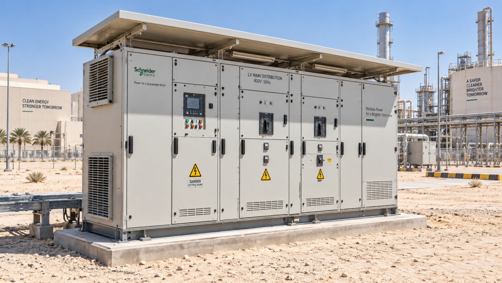
Specify temperature, dust, and corrosion as one package
Environmental protection is often written as separate items in a tender: temperature range, ingress rating, and paint finish. In service, these factors interact. A sealed steel enclosure in a hot location can become a thermal problem. An enclosure with ventilation may control heat but introduce dust. A coastal site may require stronger corrosion protection even where dust exposure is modest.
Corrosion resistance is particularly easy to under-specify. Salt-laden air, humidity, chemical vapors, washdown exposure, and condensation can degrade enclosure surfaces and hardware long before the main electrical components reach the end of their expected service life. Material selection, coating system, gasket quality, fasteners, hinges, internal supports, and cable accessories all need to be considered together.
Do not assume stainless steel is automatically the best answer. It may be justified in aggressive environments, but it increases cost and does not remove the need for a good thermal, drainage, sealing, and maintenance design. In less aggressive applications, a properly protected painted steel enclosure may be appropriate. The correct choice follows the site exposure, not a single material preference.
Confirm voltage, frequency, earthing, and utility interface early
Electrical compatibility must be confirmed before comparing panel layouts. Power systems across the region can differ by project, utility, building type, and source arrangement. The required voltage, frequency, phase configuration, neutral arrangement, earthing method, fault level, metering interface, and utility protection expectations should be stated in the technical schedule, not left for later clarification.
This matters because distribution equipment is a connected system. A main switchboard, transformer, generator connection, automatic transfer arrangement, motor control center, low-voltage feeder panel, and final distribution board must all operate coherently. A mismatch in neutral sizing, earthing philosophy, breaker pole configuration, or protection settings can create nuisance tripping, impaired fault clearance, or unsafe maintenance conditions.
Special attention is needed where the facility includes generator sets, solar inverters, battery systems, or other embedded sources. These sources can change fault current behavior, reverse-power conditions, synchronization requirements, harmonic levels, and protection coordination. The specification should define operating modes: utility only, standby generation, closed-transition transfer, parallel operation, islanded operation, or export-capable generation. Equipment suitable for a simple utility-fed building may not be suitable once multiple sources are added.
Harmonics should also be considered where the load includes variable-speed drives, uninterruptible power systems, rectifiers, data equipment, LED lighting, or large inverter-based systems. The practical question is not whether harmonics exist, but whether the transformer, neutral, busbars, capacitors, meters, and protective devices have been selected for the expected waveform and thermal effects.
Short-circuit performance is a system decision
A distribution board is not adequately specified just because its incoming breaker has a high breaking capacity. Every relevant part of the assembly must withstand and clear the available fault energy at its installed location. That includes busbars, circuit breakers, fuse assemblies, cable terminations, internal supports, and downstream panels where the prospective fault level remains significant.
The required fault rating should be based on a coordinated short-circuit study covering utility contribution, transformer impedance, generator contribution, parallel sources, and the impedance of conductors between equipment. The closer a board is to a transformer or multiple-source connection point, the more critical this becomes.
There are two separate questions: can the protective device interrupt the fault, and can the assembly withstand the electrodynamic and thermal forces until interruption occurs? Both must be addressed. Selecting a high-rated breaker within an inadequately rated enclosure or busbar system does not produce a properly rated assembly.
Protection selectivity is the next part of the decision. A fault on a small downstream feeder should ideally disconnect that feeder rather than shutting down an entire floor, process line, or facility. This requires compatible breaker characteristics, correctly chosen protective settings, and a documented coordination approach. Greater selectivity can add cost, but it has substantial value where downtime is expensive or safety systems must remain energized.
Choose an internal form that matches the operating risk
The internal arrangement of a switchboard determines how faults, maintenance work, and routine isolation are managed. Segregation between busbars, functional units, and terminals can improve safety and availability, especially in critical facilities or industrial sites where shutdown windows are limited.
A simpler construction may be entirely suitable for a small, low-risk commercial installation with straightforward maintenance. It becomes less attractive when one feeder must be serviced while adjacent sections remain live, when multiple operators work on the same assembly, or when a fault in one compartment could disrupt essential loads.
Rather than specifying the highest possible internal segregation by default, define the maintenance scenario. Consider whether outgoing feeders need to be isolated independently, whether cable termination work will occur near energized busbars, whether critical loads need physical separation, and whether future extension is expected. The answer should shape the board architecture.
Do not treat digital features as a substitute for electrical design
Smart meters, breaker communications, thermal sensors, power quality monitoring, and remote alarms can provide useful operating visibility. They are especially valuable in geographically dispersed facilities, energy-intensive sites, or buildings where preventive maintenance depends on early warning rather than frequent manual inspection.
However, digital capability should be selected around a defined operational use. If the site only needs basic energy allocation, a robust meter and clear communications interface may be sufficient. If the system will feed a building management platform, energy management platform, or remote operations center, specify the required data points, communication protocol, network topology, cybersecurity responsibilities, time synchronization, and local control behavior during communications failure.
A common mistake is purchasing “smart switchgear” without defining who will act on the data. Monitoring that is not integrated into maintenance routines becomes an added cost rather than a reliability tool. Conversely, a well-designed monitoring package can reveal overloaded feeders, abnormal temperature rise, poor power factor behavior, or recurring transfer events before they cause a shutdown.
GPEGM’s coverage of digital switchgear integration and evolving grid technologies is useful in this stage because technology trends should be translated into a project-specific requirement, not copied into a specification simply because the feature is available.
Serviceability can be more valuable than a marginally lower purchase price
Power distribution equipment is expected to remain in operation for years, so the availability of support, spare parts, documentation, and competent maintenance capability deserves a place in the technical evaluation. This does not mean choosing a supplier only on geographic presence. It means verifying that the selected design can be inspected, tested, repaired, and expanded without impractical disruption.
Ask how readily critical components can be replaced, whether breaker frames and accessories are identifiable, whether protection settings can be retrieved and restored, and whether the documentation includes single-line diagrams, wiring drawings, test records, component schedules, and operating instructions. Proprietary systems can offer strong integration, but they should not create an avoidable dependency where a minor failure requires an extended outage.
Maintainability also includes physical access. Panels need working clearance, cable termination room, door opening space, lifting provisions where relevant, and logical labeling. Dense panel layouts may save floor area at the design stage while creating difficult and risky maintenance work later.
A practical specification sequence
When preparing a request for quotation or reviewing alternatives, use this sequence to keep technical decisions in the right order:
- Define the source arrangement, load profile, expected expansion, and continuity requirements.
- Record actual environmental conditions at each equipment location, including heat, dust, humidity, corrosion exposure, and ventilation constraints.
- Establish voltage, frequency, earthing, neutral, metering, and utility interface requirements.
- Complete short-circuit and protection coordination inputs before finalizing breaker and busbar ratings.
- Select enclosure protection, cooling approach, corrosion protection, and internal segregation based on the site and maintenance scenario.
- Specify monitoring only after defining the data, control, and maintenance workflow it must support.
- Evaluate drawings, type-test evidence where applicable, documentation quality, spare-parts strategy, and service arrangements alongside price.
This order prevents a frequent tender problem: selecting an attractive panel configuration first and then trying to add environmental protection, fault-duty capability, communications, and maintainability requirements after the architecture is already fixed.
Questions that reveal weak proposals
A technically complete proposal should explain its assumptions. If an offer lists ratings without showing the installation conditions behind them, it may be difficult to compare with another proposal on a like-for-like basis. Request clarity on ambient temperature assumptions, current derating, fault withstand capability, ingress protection across all entry points, corrosion protection details, internal separation, protection settings, and the scope of factory testing.
Be cautious when a proposal uses broad phrases such as “suitable for harsh environments” without linking that claim to enclosure construction, cooling method, materials, seals, and verified operating conditions. Also question excessive standardization. A standard design can be efficient and reliable when it fits the application; it becomes a risk when site conditions are treated as optional accessories.
The strongest choice is rarely the equipment with the most features. It is the assembly whose electrical ratings, environmental design, protection strategy, and maintenance model all match the actual installation. That alignment is what turns a specification into dependable operation.
Related News
- What specifications matter for power distribution equipment in the Middle East?Oct 16, 2026Power distribution equipment Middle East: discover the essential specifications for heat, dust, corrosion, fault protection, utility compatibility, and reliable long-term operation.
- Which power distribution equipment suits Southeast Asia's humid sites?Oct 15, 2026Power distribution equipment Southeast Asia: select humidity-resistant, corrosion-protected, verified assemblies for tropical sites. Explore practical selection insights.
- What to verify before choosing a smart switchgear manufacturerOct 10, 2026Compare smart switchgears manufacturers by electrical duty, digital integration, cybersecurity, testing, and lifecycle support to select a reliable long-term partner.
- Industrial Generator Set Procurement: Verifying Ratings and Test RecordsOct 14, 2026Industrial generator set procurement guide: verify ratings, site derating, load performance, fuel runtime, and traceable factory test records before purchase.
Related News
- 00
0000-00
How to assess utility protection and control system interoperability - 00
0000-00
How energy prices affect the cost of decarbonizing industrial processes - 00
0000-00
How SCADA grid automation supports remote feeder fault isolation - 00
0000-00
How much does arc-resistant construction add to switchgear prices? - 00
0000-00
How a decarbonization process framework turns targets into action