
A power quality diagnostic investigation traces nuisance trips by recording what happened electrically before protection operated, then matching that evidence to the device’s trip logic. The useful sequence is disturbance, equipment response, and disconnection. A voltage dip recorded after a breaker opens does not establish that the supply caused the trip.
Preserve the first fault code, event history, operating state, and protection settings before resetting equipment. Repeated resets erase useful context and can expose equipment to an unresolved fault. Although a trip appears unnecessary when no damage is visible, protection may have responded correctly to a brief condition that ordinary meters missed.
Establish which device acted first
A stopped production line can generate several alarms from one initiating event. A drive trips, its contactor releases, the controller loses a ready signal, and downstream equipment reports communication or process faults. The last alarm displayed on the screen is often far removed from the initiating condition.
Collect the drive’s internal fault record, breaker or relay trip indication, controller event log, and any available power monitor records. Record whether the trip occurred during acceleration, steady operation, braking, load transfer, or the start of nearby equipment. Include recent changes to motors, cables, filters, firmware, and protection settings when they affect the suspected circuit.
Timestamp accuracy determines how confidently these records can be compared. A controller log with coarse timestamps cannot establish the order of events separated by milliseconds. Align clocks where supported, document known offsets, and use waveform triggers or shared status signals when closer timing is necessary. An alarm timestamp may represent software processing rather than the physical instant of failure.
The first decision is whether electrical supply conditions changed before the equipment began to disconnect. If the waveform disturbance follows current interruption, it may be a consequence of the trip. If it precedes the trip, its magnitude, duration, and location must still explain the protection response.
Measure at the terminals that matter
Begin at the affected equipment’s incoming supply, with voltage and current recorded together. A monitor at the main switchboard can miss a voltage drop across a damaged feeder connection, undersized conductor, or local switching device. Conversely, measurements taken only at one machine cannot establish whether the disturbance originated upstream or within that machine.
When the source is uncertain, simultaneous recordings at the machine terminals and an upstream distribution point provide stronger evidence. A sag visible at both locations suggests a shared upstream event or a sufficiently large local load affecting both points. A much deeper sag at the machine directs attention toward the intervening feeder and its connections. Current direction, load changes, and the distribution layout help distinguish these possibilities.
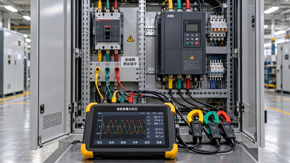
Match the voltage connections to the equipment’s actual power path. Three-phase drive inputs generally require phase-to-phase assessment; a separate control supply may depend on phase-to-neutral voltage. Stable drive input voltage does not rule out a control transformer, power supply, or contactor coil problem. Where control dropout is suspected, capture the relevant control voltage alongside the main supply event.
Instrument setup is part of the diagnosis. Incorrect phase association, reversed current probes, unsuitable probe ranges, or current sensor saturation distort the evidence. Use a power quality analyzer and accessories rated for the installation, with connections made under the site’s electrical safety procedures. Standard supply measurements also require different instruments and methods from measurements on a drive’s pulse-width-modulated output.
Capture enough detail before and after the trigger
Long recording duration alone does not guarantee a useful capture. Configure pre-trigger waveform storage so the record includes the onset of the disturbance. Retain enough post-trigger data to show current interruption, voltage recovery, and any restart attempt. Trigger levels should capture conditions relevant to the equipment’s documented operating limits without filling memory with routine fluctuations.
Use RMS event records to assess sag depth and duration, and waveform captures to examine short interruptions, phase discontinuities, and current behavior. Fast transients require sufficient measurement bandwidth and a suitable capture mode; an instrument that records voltage sags does not necessarily characterize every transient. For infrequent trips, recording should cover the operating cycles associated with previous failures.
Read the voltage and current signatures together
A voltage event becomes diagnostically useful when its timing and current response support a physical explanation. The following patterns narrow the investigation, but each needs comparison with the actual trip function and circuit arrangement.
Current magnitude alone does not distinguish cause from consequence. During a voltage sag, a drive attempting to maintain power can draw more input current within its control limits. That increase does not automatically identify the drive as the source of the sag. Its timing relative to the voltage change matters.
Likewise, voltage recovery after disconnection is not proof that the incoming supply was healthy. Removing load reduces voltage drop across source and feeder impedance. A high-resistance connection can therefore appear acceptable when the machine is idle and deteriorate only under operating current.
Separate drive faults from supply disturbances
A drive undervoltage alarm indicates that an internal voltage threshold was crossed; it does not identify the failed component. Compare the incoming AC waveform with the DC bus record, where available. A supply sag followed by bus decay supports an input disturbance. Stable AC voltage with abnormal bus behavior shifts attention toward the rectifier, precharge circuit, DC link components, or internal sensing.
Sag duration matters as much as depth. DC link energy storage, operating load, and control behavior affect ride-through. A short event tolerated at light load can stop the same drive during heavy operation. Compare the captured event with the manufacturer’s applicable limits and configured functions rather than assigning a universal acceptable voltage threshold.
Overvoltage requires a different distinction. An incoming swell can raise DC bus voltage, while a decelerating or overhauling load can return energy to the bus without an incoming voltage rise. Increasing deceleration time addresses only applications where the process permits it and regeneration is the established cause. It does not correct an incoming supply problem or a failed braking component.
An overcurrent trip with clean incoming voltage also deserves examination of acceleration demand, mechanical binding, motor condition, and output wiring. A supply-side analyzer cannot fully diagnose motor insulation stress or output switching behavior. Further measurements should follow the drive and motor manufacturers’ procedures, especially where insulation testing requires electronic equipment to be disconnected.
When harmonics or leakage appear in the record
High current distortion is common at nonlinear loads and does not, by itself, explain a trip. Assess absolute harmonic current, total RMS current, voltage distortion, loading, and the protection element involved. Current total harmonic distortion can rise at light load because the fundamental current decreases, even when harmonic current has not increased.
For a thermal trip, compare sustained loading and harmonic heating with the device’s rating and sensing method. For an instantaneous trip, examine the captured current peak and operating threshold. A harmonic summary averaged across a long interval cannot establish what operated an instantaneous element during a brief event.
Residual-current protection needs a separate measurement path. Converter filters, motor cable capacitance, and switching produce leakage components that an ordinary phase-current measurement does not characterize adequately. Measure the residual current around all live conductors of the circuit, excluding the protective conductor, with an appropriate instrument. Device type, frequency response, cumulative leakage, and actual insulation condition all affect interpretation.
Do not attribute every residual-current trip to harmless filter leakage. Moisture, damaged cables, and deteriorated insulation can produce similar symptoms. Protective conductors must remain connected, and compatibility decisions should follow the equipment and protection manufacturers’ requirements.
Choose a correction that matches the recorded cause
The evidence should identify both the initiating condition and the reason protection responded. A loose termination calls for repair and examination of associated damage. A shared sag during motor starting calls for assessment of starting current, source impedance, and feeder arrangement. Loss of control voltage may require attention to the control supply’s ride-through, even when the main drive remains energized.
Where protection coordination is implicated, compare the captured event with the actual configured trip curve, tolerance, and operating conditions. A breaker that trips after sustained loading presents a different problem from one operating instantaneously during energization. Ambient temperature, enclosure heating, prior loading, and terminal condition can influence thermal operation.
Changing a threshold or delay is justified only after confirming that the revised setting preserves conductor and equipment protection, fault clearance, and coordination. Repeatedly increasing settings until trips stop removes evidence without proving that the installation is sound.
A proposed power quality remedy also needs a defined purpose. A line reactor introduces impedance and changes drive input behavior; it does not restore missing supply energy. Harmonic filters require assessment of the network and existing capacitors. Surge protection addresses transient overvoltage exposure, while voltage sag ride-through requires a solution capable of sustaining the affected load for the relevant event.
Prove the repair under the triggering conditions
Verification should reproduce the operating state associated with the original trip as closely as the process safely allows. Capture the same electrical channels, retain comparable instrument settings, and record load, speed, starting sequence, or braking conditions. An unloaded restart provides weak evidence for a fault that appeared only during full-load acceleration.
Compare the corrected record with the original mechanism: reduced feeder voltage drop, stable control voltage, acceptable bus behavior, or removal of abnormal leakage. An absence of trips during a quiet period is less persuasive when the initiating disturbance has not recurred.
Retain the waveforms, clock alignment notes, fault codes, instrument configuration, protection settings, and repair details together. The resulting record should show the observed sequence, the evidence supporting the cause, and the operating conditions covered by verification. Any remaining uncertainty should be tied to a specific missing measurement or event.
Related News
- How to size a containerized energy storage system for peak shavingNov 04, 2026Size a containerized energy storage system for peak shaving. Learn to assess load data, demand charges, battery capacity and costs for a reliable project.
- Can an electrical grid platform integrate with legacy SCADA systems?Nov 02, 2026Can an electrical grid platform for utilities integrate with legacy SCADA? Explore protocols, cybersecurity and pilot steps to reduce risk and protect reliability.
- Can an electrical grid intelligence dashboard detect outages?Nov 01, 2026Can an electrical grid intelligence dashboard detect outages? Explore the data, detection methods, and essential tests that reveal how reliably it identifies power interruptions.
- How to select a circuit breaker for switchgear based on fault currentOct 31, 2026Choose the right circuit breaker for switchgear by evaluating fault current, interrupting capacity and coordination. Explore the essential checks.
Related News
- 00
0000-00
How to assess a smart grid device manufacturer's interoperability - 00
0000-00
How to size a containerized energy storage system for peak shaving - 00
0000-00
How to use a global power matrix for procurement negotiations - 00
0000-00
Can an electrical grid platform integrate with legacy SCADA systems? - 00
0000-00
Can an electrical grid intelligence dashboard detect outages?