
Redundancy improves industrial power system reliability when a failed component can be isolated and the remaining supply can support critical loads within their interruption limits. A second source earns its place only if the complete path to the load survives the failure being addressed. Shared switchgear, control power, cable routes, or cooling can defeat an otherwise convincing N+1 or 2N design.
The selection decision therefore starts with three questions: which failures must the system withstand, how long can each process tolerate a disturbance, and what capacity remains during maintenance? If the answers are unclear, adding equipment risks increasing complexity without reducing production interruptions.
Define success at the load terminals
A healthy backup generator does not establish continuity at a motor drive, control cabinet, or process heater. The useful boundary extends from the energy source through protection, switching, distribution, and the load’s own input arrangement. Reliability must be judged against the electrical conditions that keep the process running.
Separate loads by their actual interruption tolerance. A heater might tolerate a supply break while retaining enough thermal energy to preserve production. A control system could reset during the same event, forcing the whole line through a restart sequence. A large drive might remain electronically powered yet trip because its DC bus falls below the undervoltage threshold.
For each critical load, establish the allowable interruption duration, acceptable voltage excursion, restart behavior, and consequence of losing associated auxiliaries. Include lubrication pumps, cooling fans, instrument supplies, and communication equipment where their loss stops the process. Supplying the main machine through two feeders achieves little if a single auxiliary panel remains essential to operation.
Restoring voltage is not necessarily restoring production. A transfer that completes successfully can still leave contactors open, drives faulted, and process permissives unfulfilled. Acceptance criteria should identify whether success means uninterrupted operation, automatic recovery, or a controlled shutdown.
Choose N+1 or 2N around the failure being covered
N represents the capacity needed to serve the defined load under stated operating conditions. N+1 adds one redundant capacity unit; 2N provides two complete systems, each capable of supporting that load. These labels describe capacity arrangements, but they do not establish how effectively faults are contained.
An N+1 plant can be the stronger choice when module failure dominates the interruption risk and shared infrastructure is sufficiently robust. A 2N arrangement becomes more valuable when distribution faults or maintenance outages must also be tolerated. Its benefit depends on preserving separation throughout the installation.
Define the operating state behind the redundancy claim. A system that withstands one failure with every component available might lose that capability while a breaker or UPS module is being serviced. If maintenance and a subsequent fault must both be covered, evaluate that combined condition explicitly.
Trace where the two paths become one
Start with the single-line diagram, then compare it with physical routes and auxiliary services. Two incoming feeders could share an upstream substation. Separate generators might depend on one fuel transfer pump, starting battery charger circuit, or ventilation system. Duplicate controllers can receive power from the same small DC supply.
Physical separation matters because one event can affect several electrically independent components. Cables in the same trench share exposure to excavation damage and flooding. Adjacent switchboards can share exposure to fire or water ingress. The required separation should follow the credible hazards at the site.
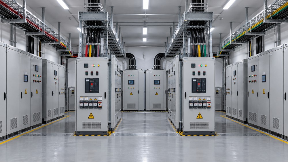
A useful diagram shows both power paths, their protective devices, transfer points, and supporting services. Mark every shared element and ask what happens if it fails, becomes unavailable, or sends an incorrect command. This often reveals a more productive investment than adding another source: separating control power, moving a cable route, or removing a shared auxiliary dependency.
Control independence deserves particular attention. A common communication network or supervisory controller can issue an erroneous shutdown to otherwise independent systems. Local protection and essential transfer functions should have defined behavior during communication loss, controller failure, and loss of auxiliary power. Document whether each condition causes continued operation, a blocked transfer, or a trip.
Protection must isolate faults without sacrificing healthy loads
Redundancy helps with a failed source only if the failure stays within its intended boundary. A downstream short circuit that trips the main incomer can remove healthy loads alongside the faulted branch. Feeding that same uncleared fault from the alternate source simply repeats the interruption.
Selective protection requires coordination across every intended operating mode. Utility supply, generator supply, UPS operation, and bus-tie configurations produce different fault-current conditions. A generator-fed system can provide insufficient sustained fault current to operate an instantaneous element assumed to work under utility supply. An inverter-based source has its own current-limiting behavior, which must be considered with downstream protective devices.
Review time-current coordination, earth-fault protection, breaker clearing behavior, and equipment withstand together. Where intentional delays preserve selectivity, assess their effect on equipment damage and arc-flash exposure. Faster clearing and wider selectivity do not automatically improve together.
Parallel operation introduces another constraint. Closing a bus tie or operating sources together can raise prospective fault current beyond equipment ratings. Any permitted configuration must remain within switchgear interrupting and withstand capabilities. Interlocks should prevent prohibited states, including those reachable during manual operation or maintenance.
Transfer logic must distinguish source loss from a downstream fault. Alternate power should not be connected indiscriminately to a faulted bus. The necessary blocking and isolation logic depends on the protection arrangement and must be demonstrated through coordinated functional tests.
Match transfer performance to the process
A transfer-time specification covers only part of the interruption. The load experiences a sequence: abnormal supply detection, intentional delay, switching, alternate-source acceptance, voltage recovery, and equipment response. For a standby generator, engine starting and stabilization also sit inside that sequence unless stored energy bridges the gap.
Compare the complete disturbance with verified load ride-through behavior. A UPS supporting control electronics can preserve logic while power drives coast down, but it does not maintain mechanical output unless the drive power is also supported. Stored energy must cover the required load and duration at the relevant battery condition and temperature.
Transfer between sources also raises synchronization questions. Open-transition switching introduces a break. Closed-transition switching requires acceptable synchronism and authorization for the resulting parallel operation. A static transfer switch offers fast switching under suitable conditions, but its performance still depends on source quality, phase relationship, fault location, and load characteristics.
Motor buses need special treatment. Rotating motors retain residual voltage after disconnection, and reconnecting an alternate source at an unfavorable phase relationship can create damaging current and torque transients. The transfer method must account for motor decay, source phase angle, and the mechanical process. A transfer time that suits electronic loads is not automatically suitable for a motor bus.
Include retransfer in the evaluation. Returning to the preferred source introduces another disturbance unless the arrangement specifically avoids it. Stable-source timers and controlled retransfer sequences help prevent repeated switching during an unstable supply recovery.
Verify surviving capacity under dynamic conditions
Nameplate capacity alone does not prove that the remaining system will carry the process. Evaluate the surviving path after the defined failure, including ambient-temperature derating, reactive power demand, harmonics, phase imbalance, and load growth already committed to the project.
The transition can be more demanding than steady operation. Motors restarting together, transformer energization, and UPS battery recharge can impose a combined demand that the alternate source cannot accept without excessive voltage or frequency deviation. A generator with adequate continuous capacity can still struggle with the required load step.
Load sequencing and selective shedding can make a smaller redundant arrangement effective when process priorities permit it. The sequence must preserve essential auxiliaries before enabling dependent equipment. Shedding logic also needs a defined response to failed measurements or communications; otherwise the capacity strategy relies on another unexamined single point of failure.
For dual-input equipment, confirm how power is shared and what happens when one input disappears. Each surviving upstream path must accommodate the resulting load transfer without overloading its cables, protective devices, or UPS capacity.
Maintenance and testing determine whether redundancy remains available
A redundant system has practical value when equipment can be isolated, proved safe, serviced, and returned without interrupting critical loads. Maintenance bypasses require the same scrutiny as normal power paths. A bypass that removes conditioning or protection changes the exposure of the load for the entire maintenance period.
Draw the switching sequence for representative work: replacing a transfer switch, servicing a UPS, testing a generator, or maintaining a bus section. Identify which loads remain supplied, which protective functions remain active, and whether the remaining path still has adequate capacity. Unclear isolation boundaries and complicated temporary connections increase the chance of an incorrect switching action.
Commissioning evidence should address the complete failure response. Source start tests alone do not establish that the system will detect a disturbance, isolate the correct section, transfer successfully, and maintain the process. Test plans should include loss of control power, unavailable alternate sources, failed transfer commands, and restoration sequences where these conditions are relevant. Fault responses requiring hazardous conditions should be verified through suitable simulation, injection testing, or other controlled methods.
Recorded voltage, frequency, switching events, and load behavior provide stronger acceptance evidence than a simple “transfer successful” indication. Periodic testing must also expose dormant faults in standby equipment without creating an uncontrolled production disturbance.
Approve the architecture against demonstrable failure coverage
Compare alternatives using the same load boundary and operating assumptions. Separate uninterrupted process operation from rapid restoration: the first concerns avoiding a disruptive event, while the second improves availability by shortening recovery. A design can perform well on one measure and poorly on the other.
Any numerical reliability model should include shared failures, transfer failures, maintenance states, and repair assumptions. Treating two supply paths as statistically independent when they share essential infrastructure produces an optimistic result. Where failure data are weak, a transparent scenario assessment is more useful than a precise-looking availability figure.
The additional lifecycle cost is justified when the architecture demonstrably covers consequential failures that a simpler design leaves exposed. Before acceptance, every claimed redundancy benefit should connect to an identifiable failure, a functioning isolation or transfer response, and a load that remains within its operating limits.
Related News
- How to size a containerized energy storage system for peak shavingNov 04, 2026Size a containerized energy storage system for peak shaving. Learn to assess load data, demand charges, battery capacity and costs for a reliable project.
- Can an electrical grid platform integrate with legacy SCADA systems?Nov 02, 2026Can an electrical grid platform for utilities integrate with legacy SCADA? Explore protocols, cybersecurity and pilot steps to reduce risk and protect reliability.
- Can an electrical grid intelligence dashboard detect outages?Nov 01, 2026Can an electrical grid intelligence dashboard detect outages? Explore the data, detection methods, and essential tests that reveal how reliably it identifies power interruptions.
- How to select a circuit breaker for switchgear based on fault currentOct 31, 2026Choose the right circuit breaker for switchgear by evaluating fault current, interrupting capacity and coordination. Explore the essential checks.
Related News
- 00
0000-00
How to assess a smart grid device manufacturer's interoperability - 00
0000-00
How to size a containerized energy storage system for peak shaving - 00
0000-00
How to use a global power matrix for procurement negotiations - 00
0000-00
Can an electrical grid platform integrate with legacy SCADA systems? - 00
0000-00
Can an electrical grid intelligence dashboard detect outages?