
What Circuit Breaker Rating Does an Industrial Panel Need?
What circuit breaker rating is needed for an industrial panel? There is no single amperage that fits every installation. The correct selection must carry the calculated load, protect the conductors, tolerate legitimate starting currents, and safely interrupt the available fault current. It must also work within the panel assembly’s ratings.
That last point matters. A breaker marked 400 A does not automatically make its enclosure a 400 A panel, and a high interrupting rating does not automatically give the complete assembly an equivalent short-circuit current rating. Before choosing a catalog number, separate these ratings and establish what the installation actually requires.
Start with the panel, not the breaker catalog
“Industrial panel” can mean a distribution panelboard, an industrial control panel, a motor control center, or a switchboard. These assemblies do not all follow the same construction and application rules. A control panel containing contactors, drives, and terminal blocks needs a different assessment from a panelboard distributing power to independent branch circuits.
Record the supply voltage, phase arrangement, frequency, grounding system, assembly nameplate information, and incoming conductor details. Then identify whether the proposed breaker is the main incoming device, a feeder breaker upstream, or a branch-circuit device inside the panel. Its protective role changes the selection.
Four ratings need separate checks:
- Current rating or trip setting: the current the breaker is designed or adjusted to carry under specified conditions.
- Voltage rating: suitability for the actual supply voltage and grounding arrangement, including any restrictions on slash-rated devices.
- Interrupting rating: the fault current the breaker can safely interrupt at its rated voltage.
- Assembly short-circuit rating: the fault-current capability of the complete panel, subject to its documented construction and protective-device conditions.
For adjustable breakers, frame size is another distinction. A 400 A frame may have a lower-rated trip unit or an adjustable long-time pickup. Buying by frame size alone can produce the wrong protection.
Build a load calculation that reflects how the plant operates
Prepare a load schedule rather than adding every branch-breaker handle rating. Branch breakers may be sized to accommodate motor starting or equipment-specific protection requirements; their ratings do not represent actual operating demand.
List equipment input current, operating duration, starting method, and which loads run together. Separate motors, resistance heating, lighting, receptacle loads, drives, and other power-electronic equipment. Apply demand or noncoincident-load allowances only where the governing rules permit them and the operating arrangement supports the assumption.
For an NEC-based installation, a continuous load is generally one whose maximum current is expected to continue for three hours or more. Ordinary feeder sizing commonly requires 125% of continuous load plus 100% of noncontinuous load, subject to applicable exceptions and equipment-specific rules. Do not apply that shortcut indiscriminately to motor groups, welders, or other specially regulated equipment.
A simple calculation—and its limits
Consider a hypothetical feeder with 120 A of continuous load and 60 A of noncontinuous load. Assume these are already established line-current values and no special load rules apply:
Calculated requirement = (120 A × 1.25) + 60 A = 210 A.
A 225 A breaker could be a candidate standard size. It is not yet an approved selection. The conductors, terminals, panel bus, equipment instructions, and fault ratings must support it. Any rule allowing a next-higher standard overcurrent-device rating must also be checked rather than assumed.
A listed 100%-rated breaker assembly can change the continuous-load treatment when installed under its specified conditions. Simply finding “100%” in a brochure is not enough: enclosure, conductor, and installation requirements are part of that rating.
For a balanced three-phase load, current can be estimated from apparent power using I = kVA × 1,000 ÷ (√3 × line-to-line voltage). If starting from motor shaft power, efficiency and power factor must also be considered. Use the current basis required by the applicable code; some motor calculations use code-table values rather than nameplate running current.
Motors and drives change the protection problem
A motor-heavy panel may run comfortably below its incoming breaker rating and still trip when a large motor starts. Increasing the breaker amperage without reviewing the trip curve is a poor first response. The problem may be instantaneous pickup, acceleration time, simultaneous starting, or an equipment fault.
Motor circuits separate overload protection from short-circuit and ground-fault protection. Under NEC Article 430, motor branch-circuit protective devices and motor feeders have specific sizing provisions. A branch breaker can therefore be larger than the motor’s running current might suggest, while a separate overload device protects against sustained overload.
For a feeder supplying several motors, do not simply add their branch-breaker ratings. Apply the relevant motor-feeder rules and include other loads as required. Check time-current curves against the expected starting sequence.
Variable-frequency drives need another check: use the drive’s input requirements and specified upstream protection, not just the motor output current. A drive’s documented short-circuit rating may depend on a particular fuse class or breaker combination. Soft starters likewise need coordinated protection consistent with their instructions.
If nuisance trips follow a drive retrofit, investigate before upsizing. Input charging behavior, protection settings, wiring, and operating sequences may have changed even though the motor power stayed the same.
Check fault current separately from operating current
Normal load calculations do not establish fault duty. Available short-circuit current depends on the source, transformer impedance, conductor impedance, and contributions from motors or other connected sources.
For an illustrative installation with 35 kA of available symmetrical fault current at the panel, a breaker rated to interrupt only 25 kA at the system voltage is insufficient as a standalone selection. A higher-rated breaker may solve that device-level issue, but the panel assembly must also be suitable for the available fault current.
A high-interrupting-capacity main breaker does not automatically raise the short-circuit current rating, or SCCR, of downstream contactors, distribution blocks, drives, and other components. For industrial control panels, UL 508A Supplement SB provides an established method for determining SCCR where applicable. Panelboards and other assemblies require their own applicable evaluation.
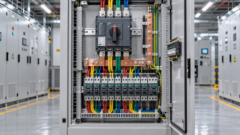
Treat the one-line diagram as a chain: source fault current, upstream protection, feeder, panel main, and downstream components. Every relevant link needs adequate capability or a documented, permitted protective combination.
Series-rated combinations and current-limiting devices can help, but only within their evaluated conditions. Do not infer protection from a breaker’s interrupting rating alone. Interrupting capacity describes its ability to clear a fault; it does not, by itself, establish the let-through energy experienced by downstream equipment.
Let conductor and installation limits constrain the choice
The breaker must coordinate with allowable conductor ampacity after applicable temperature corrections and adjustment factors. Check terminal temperature ratings, conductor material, cable grouping, installation method, and enclosure conditions. A conductor’s insulation temperature rating does not automatically authorize using that temperature column at its terminals.
Hot production areas deserve attention. A breaker selected from reference-condition data may behave differently inside a heavily loaded enclosure beside furnaces or process heaters. Use the manufacturer’s ambient-temperature and enclosure guidance rather than adding an arbitrary amperage margin.
Check the neutral where nonlinear single-phase loads are significant; phase-current totals alone may not capture harmonic heating. Also verify pole configuration and any neutral switching requirements against the supply system and local rules.
Future capacity is best handled as an explicit design allowance. If expansion is expected, specify suitable bus capacity, enclosure space, and feeder infrastructure. Do not install an oversized protective setting today unless the existing circuit and applicable rules support it.
NEC and IEC ratings require different reading
In NEC-based work, relevant requirements may include Articles 110, 215, 240, 409, and 430, depending on the assembly and loads. Use the locally adopted edition and confirm requirements with the authority having jurisdiction. A component’s listing does not establish compliance of the complete installation.
IEC-based projects commonly involve IEC 60947-2 for industrial circuit breakers and the applicable IEC 61439 assembly requirements. IEC breaker data may distinguish ultimate short-circuit breaking capacity, Icu, from service short-circuit breaking capacity, Ics. Where continuity after fault interruption matters, reviewing Icu alone misses an important selection criterion.
Assembly ratings may include short-time withstand current, Icw, or conditional short-circuit ratings tied to specified protective devices. These are not interchangeable with a North American SCCR marking. International procurement should compare the documented performance and applicable standards, not merely matching ampere and kiloampere numbers.
Before releasing the breaker specification
A defensible specification records the calculated load, breaker current or trip settings, voltage and poles, interrupting rating at that voltage, assembly fault rating, conductor requirements, and any mandatory protective-device combinations. Adjustable settings should be documented, not left to a commissioning guess.
Review coordination with upstream and downstream devices, particularly where one trip could stop an entire process. Longer delays may improve selectivity but can increase incident energy; coordination and arc-flash assessments should be considered together.
For GPEGM’s coverage of power equipment, distribution technology, and motion drives, this is a useful dividing line between a component comparison and an engineering decision: the breaker must fit the electrical system, not just the purchasing specification.
If the load schedule, available fault current, or panel rating is missing, the selection is not ready. Obtain those records and have a qualified electrical professional verify the design before ordering a larger breaker or changing trip settings.
Related News
- How to size a containerized energy storage system for peak shavingNov 04, 2026Size a containerized energy storage system for peak shaving. Learn to assess load data, demand charges, battery capacity and costs for a reliable project.
- Can an electrical grid platform integrate with legacy SCADA systems?Nov 02, 2026Can an electrical grid platform for utilities integrate with legacy SCADA? Explore protocols, cybersecurity and pilot steps to reduce risk and protect reliability.
- Can an electrical grid intelligence dashboard detect outages?Nov 01, 2026Can an electrical grid intelligence dashboard detect outages? Explore the data, detection methods, and essential tests that reveal how reliably it identifies power interruptions.
- How to select a circuit breaker for switchgear based on fault currentOct 31, 2026Choose the right circuit breaker for switchgear by evaluating fault current, interrupting capacity and coordination. Explore the essential checks.
Related News
- 00
0000-00
How to assess a smart grid device manufacturer's interoperability - 00
0000-00
How to size a containerized energy storage system for peak shaving - 00
0000-00
How to use a global power matrix for procurement negotiations - 00
0000-00
Can an electrical grid platform integrate with legacy SCADA systems? - 00
0000-00
Can an electrical grid intelligence dashboard detect outages?