
Can one motor controller support different motor loads? Usually, yes, but only when the controller, motor, load profile, and protection settings are matched deliberately.
Rated power alone is not enough. Engineers must compare continuous torque, peak torque, speed range, acceleration requirements, duty cycle, feedback method, and thermal limits.
For plant managers and energy decision-makers, the practical question is whether controller flexibility reduces inventory and commissioning cost without increasing downtime, failures, or safety risks.
A correctly selected drive can operate multiple compatible load conditions. An incorrectly selected one may trip repeatedly, overheat motors, damage mechanical equipment, or compromise process quality.
Start With the Load Profile, Not the Motor Nameplate
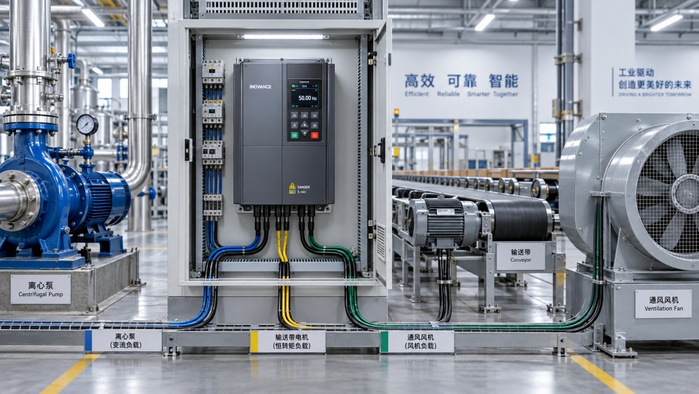
The first compatibility check is the driven load. A motor controller regulates electrical energy, but the mechanical load determines how much torque and speed the application demands.
Constant-torque loads require nearly the same torque across their operating range. Conveyors, extruders, mixers, crushers, and positive-displacement pumps commonly fit this category.
Variable-torque loads behave differently. Fans and centrifugal pumps generally need torque proportional to speed squared, while their power demand rises approximately with speed cubed.
That distinction matters because a controller serving a fan may appear generously sized at partial speed, yet become overloaded when reassigned to a conveyor or mixer.
Constant-power loads add another consideration. Winding machines, machine-tool spindles, and traction applications may need reduced torque as speed increases while maintaining output power.
Before reusing a controller, document the required torque-speed curve for each application. Compare normal operation, startup, acceleration, deceleration, overload events, and emergency stopping conditions.
Inertia is often underestimated. A lightly loaded motor can still require substantial acceleration current when rotating mass is high, especially in large fans, rollers, centrifuges, and flywheel systems.
A controller that runs a steady-state pump successfully may therefore fail during rapid starts on a high-inertia conveyor. The issue is dynamic torque, not necessarily nominal power.
Understand the Difference Between Continuous and Peak Current
Motor controllers are normally specified with continuous current and short-duration overload capability. Both ratings must be evaluated when one controller supports different motor loads.
Continuous current determines whether the controller can sustain the application during normal production. Peak current determines whether it can handle starting torque, acceleration, and temporary disturbances.
Many variable frequency drives provide overload ratings such as 110 percent, 150 percent, or 200 percent for a defined duration. These ratings are not interchangeable.
A heavy-duty conveyor may need 150 percent torque for sixty seconds. A fan application may only require modest overload capacity because its starting torque is comparatively low.
Controller selection should therefore use the worst credible operating condition, rather than the average current shown during stable production. Average values can conceal short damaging peaks.
Also check the motor current rating rather than relying exclusively on kilowatt or horsepower. Motors with similar power ratings can have different full-load currents, efficiencies, and service factors.
Where multiple loads are planned, create a current margin policy. Margin should account for ambient temperature, enclosure heat, harmonic conditions, supply voltage variation, and expected production expansion.
Excessive oversizing is not automatically beneficial. It can raise capital cost, complicate protection coordination, reduce low-load control resolution, and mask mechanical problems during commissioning.
Motor Type and Control Method Must Remain Compatible
A single controller cannot necessarily operate every motor type. Compatibility depends on whether the drive is designed for induction motors, permanent magnet motors, servo motors, or reluctance motors.
Standard scalar volts-per-hertz control can serve many induction-motor loads, particularly pumps and fans. However, it may not deliver the low-speed torque accuracy needed for demanding machinery.
Sensorless vector control improves torque response and speed regulation. It is frequently suitable for conveyors, hoists, mixers, compressors, and other applications with changing mechanical resistance.
Closed-loop vector or servo control may be necessary where positioning, tension control, rapid reversals, or precise synchronization are essential. Encoder feedback changes both capability and commissioning requirements.
Permanent magnet motors require compatible algorithms, parameter sets, and sometimes encoder or resolver feedback. Connecting them to a general induction-motor drive without validation can produce poor control or damage.
When switching controllers between motors, verify voltage class, base frequency, pole count, current rating, insulation system, and feedback interface. Do not assume similar physical size indicates compatibility.
Motor tuning is equally important. Autotuning identifies electrical parameters used by advanced control algorithms. A stored parameter set for one motor should not be applied casually to another.
For organizations with interchangeable assets, maintain validated motor-controller pairing records. This reduces commissioning errors and provides a traceable basis for maintenance and spare-drive decisions.
Speed Range, Cooling, and Duty Cycle Often Set the Real Limit
Motor speed capability is not defined by the controller alone. The motor, driven equipment, bearings, lubrication, cooling arrangement, and process constraints all impose operating limits.
At low speed, a standard self-cooled motor receives less airflow from its shaft-mounted fan. Continuous high-torque operation may overheat the motor despite acceptable controller current readings.
Separately powered cooling fans, inverter-duty motors, or larger motor frames can extend low-speed capability. These measures should be evaluated before assigning a controller to a demanding low-speed load.
High-speed operation introduces different risks. Mechanical balance, bearing speed ratings, rotor integrity, gearbox limits, pump cavitation, and fan blade stresses may become more important than electrical limits.
Duty cycle determines how long a load runs, rests, accelerates, or overloads. A controller acceptable for intermittent lifting duty may be unsuitable for continuous extrusion or twenty-four-hour pumping.
Regenerative events deserve special attention. Loads that decelerate quickly or are driven by gravity can return energy to the DC bus, creating overvoltage trips without braking hardware.
Braking resistors, regenerative modules, active front ends, or longer deceleration ramps may be required. The proper solution depends on energy level, cycle frequency, grid requirements, and process safety.
For multi-load facilities, use a duty-cycle worksheet rather than a simple nameplate comparison. It should calculate thermal loading over the entire operating cycle, including abnormal but foreseeable events.
Protection Settings Need to Change With the Application
A controller may physically operate several loads, yet remain poorly protected if its configuration stays unchanged. Protection parameters must reflect the motor and mechanical equipment currently connected.
Electronic overload settings should match the motor full-load current, service conditions, and thermal behavior. Leaving settings based on a larger motor can prevent timely overload protection.
Conversely, settings based on a smaller motor may cause nuisance trips. Frequent resets are not a solution because they can hide load binding, bearing failure, phase imbalance, or cooling problems.
Set acceleration and deceleration ramps for the actual inertia and process needs. Aggressive ramps may overcurrent the drive, slip belts, stress couplings, or create unacceptable pressure transients.
Torque limits can protect mechanical equipment, but poorly selected limits may prevent successful starting. Establish limits using measured process demand and equipment manufacturer guidance whenever available.
Minimum and maximum speed limits also protect the system. Pumps may suffer inadequate lubrication at low speed, while fans, compressors, and gearboxes can face mechanical damage above rated speed.
Fault response should be specific to the operational consequence. Some processes can coast safely after a fault, while others require controlled stopping, braking, isolation, alarm escalation, or standby transfer.
Configuration management is essential when controllers are repurposed. Store parameter backups by machine, revision-control changes, and require a documented commissioning check before returning equipment to service.
When a Shared Controller Strategy Creates Business Value
Using standardized motor controllers across compatible applications can reduce spare inventory, simplify technician training, and improve sourcing resilience during supply disruptions or project expansions.
A common controller platform can also improve data visibility. Shared communications protocols and diagnostics make it easier to compare energy use, fault patterns, load trends, and maintenance needs.
For distributed industrial sites, standardization supports faster replacement. A stocked drive can be configured for an approved motor-load combination instead of waiting for an application-specific unit.
The financial case is strongest when loads belong to a defined compatibility family. Examples include similar induction motors operating pumps, fans, conveyors, or mixers within known current and torque limits.
However, standardization should not become forced interchangeability. High-performance motion systems, hoists, safety-critical equipment, and specialized permanent magnet motors often justify dedicated controller selections.
Decision-makers should compare savings from reduced stock against the cost of engineering controls. These controls include parameter libraries, labeling, training, commissioning procedures, and protective hardware.
Energy performance must also remain part of the evaluation. A variable frequency drive can reduce energy consumption substantially on variable-torque loads, particularly pumps and fans operating below full speed.
Yet efficiency gains depend on control strategy and system design. Throttling, oversized pumps, poor ductwork, inappropriate setpoints, and inefficient motors can limit the value of speed control.
A Practical Compatibility Checklist Before Reusing a Drive
Begin by confirming that supply voltage, phase arrangement, frequency, grounding method, and available short-circuit protection meet the controller manufacturer's installation requirements.
Next, compare controller continuous current and overload rating with the motor current and the application torque profile. Use actual operating data whenever it is available.
Verify motor type, control mode, feedback requirements, cable length limits, output reactor needs, insulation suitability, and electromagnetic compatibility requirements for the proposed installation.
Review the load's inertia, acceleration time, stopping method, reverse operation, regenerative energy, and frequency of starts. These factors frequently determine whether the drive remains within limits.
Check thermal conditions at both the controller and motor. Consider cabinet ventilation, altitude, airborne contamination, ambient temperature, low-speed motor cooling, and production duty cycle.
Update motor nameplate data, overload protection, speed limits, ramp settings, torque limits, fault actions, and communication parameters. Verify that obsolete settings are removed or clearly segregated.
Commission under controlled conditions. Record startup current, running current, speed stability, motor temperature, controller temperature, vibration, and fault history before approving normal production operation.
Finally, retain the results in an asset register. A documented compatibility matrix helps maintenance teams identify approved substitutions and prevents unsafe decisions during urgent breakdown repairs.
Conclusion: One Controller Can Serve Different Loads, Within Defined Boundaries
One motor controller can support different motor loads when electrical ratings, motor technology, torque-speed requirements, thermal conditions, and protection settings are all compatible.
The governing principle is simple: select and configure the controller for the most demanding verified load condition, not for the least demanding application it has previously operated.
For pumps and fans, controller sharing may be straightforward when voltage, current, and operating envelopes align. For conveyors, hoists, servo systems, and high-inertia machinery, deeper analysis is required.
Organizations gain the most value by pairing equipment standardization with disciplined engineering records, validated parameters, and condition-based monitoring. That approach supports reliability, efficient maintenance, and scalable electrification.
Ultimately, the right question is not whether a controller can make another motor turn. It is whether it can operate that motor load safely, efficiently, and predictably over its full lifecycle.