
Why a DC Motor Can Run Cool at Steady Load but Overheat in Real Service
Why does a DC motor overheat under variable load? In most field situations, the short answer is that the motor is repeatedly asked to produce more torque than its thermal system can absorb. The problem is rarely just “too much load” in a simple sense. A motor may operate within its nameplate current during a steady test and still run dangerously hot in a conveyor, hoist, pump, winding line, automated gate, battery-powered vehicle, or process machine where torque demand changes every few seconds.
Variable load creates current peaks, speed swings, repeated acceleration, and sometimes unstable control behavior. Those electrical and mechanical events generate heat faster than the frame, fan, bearings, brushes, and surrounding air can remove it. By the time a thermal switch trips, the damage may already include shortened insulation life, brush wear, weakened commutation, or a permanently reduced magnetic margin.
The practical mistake is to judge a DC motor only by rated power. In dynamic duty, torque, current waveform, duty cycle, cooling conditions, and the load’s inertia usually tell the more useful story.
The Main Heat Source: Current Rises Faster Than Most Teams Expect
For a conventional DC motor, torque is closely related to armature current. When the driven machine demands more torque, armature current rises. Copper losses then rise approximately with the square of current, expressed as I²R loss. This is why a modest-looking increase in current can create a disproportionate increase in winding heating.
Under variable load, the motor does not see one stable current value. It sees a sequence of peaks and valleys. A packaging machine may accelerate a mechanism, pause, index, and accelerate again. A crusher may encounter intermittent hard material. A pump may experience changing differential pressure. Each event can pull high current from the supply or controller. If those peaks are frequent, the motor’s average thermal loading may become excessive even when the measured average shaft load appears acceptable.
A clamp meter that reports only a smooth average can hide the real problem. For troubleshooting, it is often more useful to capture current over time with a drive log, oscilloscope, power analyzer, or controller telemetry. The important questions are: how high are the peaks, how long do they last, how often do they repeat, and does the motor have enough time to cool between them?
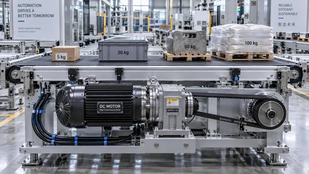
Repeated Starts, Reversals, and Low-Speed Operation Are Particularly Harsh
Starting current is naturally high because back electromotive force is near zero at standstill. Back EMF increases as a DC motor gains speed, helping limit armature current. When a motor is repeatedly started, jogged, plugged, or reversed before reaching normal speed, it spends too much time in the condition where current is highest.
This is common in indexing equipment and in systems where production logic has changed but the original motor was never re-evaluated. A machine that once made a few movements per minute may later be asked to operate at a much shorter cycle time. The motor may still complete the motion, so the problem is overlooked until heat, brush dust, or nuisance trips appear.
Low-speed operation deserves the same caution. Many motors rely on a shaft-mounted fan. Reduce shaft speed and airflow falls at precisely the moment the motor may be producing high torque. A DC motor turning slowly under heavy load can therefore be thermally worse off than the same motor running faster at a similar torque. This is not a minor detail in web tensioning, position control, lifting, and extrusion equipment.
Variable Load Does Not Always Mean an Electrical Fault
Electrical checks are essential, but many overheating problems begin on the mechanical side. A motor cannot distinguish between useful production torque and torque wasted in friction, misalignment, or a poorly selected transmission ratio. It simply draws current to meet demand until the supply, drive, protection system, or motor itself reaches a limit.
Common mechanical contributors include tight or damaged bearings, belt over-tension, coupling misalignment, gearbox drag, an intermittently sticking process load, and a load inertia that is too large for the chosen acceleration profile. A fan blade rubbing its shroud or a pump with debris at the impeller can create a variable torque signature that looks like a control problem at first glance.
In practice, a useful test is to compare the current profile with the driven equipment connected and, where it is safe and permitted, with the motor mechanically unloaded. If the motor still heats rapidly with no load, attention turns to electrical condition, cooling, brush gear, or the drive. If current peaks disappear when the process load is removed, the mechanical system deserves closer inspection.
Speed Control and Power Quality Can Add Their Own Heating
A DC drive is not merely a source of voltage. Its current limit, acceleration ramp, speed-loop tuning, switching behavior, feedback quality, and braking arrangement all influence motor heating. A poorly tuned speed loop may hunt around a setpoint. The shaft speed may appear almost stable to an operator, while the controller continually commands corrective current pulses. That repeated correction becomes heat in the armature and can also aggravate mechanical resonance.
Current limit settings need careful judgment. Setting a high limit may prevent a drive fault during a difficult acceleration, but it does not make the motor more thermally capable. It can simply allow the machine to keep imposing damaging current for longer. Conversely, an overly conservative limit can cause speed droop, which may tempt operators to increase the setpoint or alter process settings, creating a different problem.
Supply voltage variation matters as well. With inadequate armature voltage, a motor may struggle to reach commanded speed and remain in a high-current, low-back-EMF condition. On separately excited machines, field supply issues can be more serious: weak field can increase speed at light load, yet the motor’s torque and commutation behavior may no longer match the intended operating range. These conditions should be assessed by qualified personnel because incorrect field adjustments can quickly create a hazardous overspeed risk.
Heat May Be Trapped, Not Created by the Load Alone
A motor that was acceptable on an open test bench can overheat inside a cabinet, beneath a machine guard, or beside a furnace, compressor, or other heat source. Dust-filled cooling passages, blocked fan intakes, oil contamination, and recirculating hot air are ordinary causes. So is an ambient temperature that differs materially from the conditions assumed when the motor was selected.
The location of heat offers clues. A broadly hot frame may point to sustained overload or poor ventilation. A hot bearing housing points more toward lubrication, bearing condition, side loading, or alignment. Heating concentrated around brushes and the commutator can indicate poor commutation, incorrect brush seating, contamination, or a commutator surface that needs attention. Infrared inspection can help compare locations, but surface temperature alone does not reveal winding temperature. Emissivity, reflective surfaces, and viewing angle can mislead an infrared reading, so it should be treated as one piece of evidence rather than the verdict.
A Better Troubleshooting Sequence Than “Replace the Motor”
When a DC motor overheats under variable load, replacing it with the same rating is often the fastest way to repeat the failure. Start by defining the actual duty cycle: acceleration time, running speed, dwell time, reversal frequency, load variation, and ambient conditions. Then record armature current and speed over several normal production cycles, including the troublesome part of the process.
Next, inspect the mechanical train. Check alignment, belt and chain tension, gearbox condition, couplings, bearings, and the process itself. Do not ignore changes made upstream or downstream of the motor; a new product format, altered material, or revised machine timing can change torque demand without any change to the motor circuit.
After that, examine the drive configuration and feedback. Verify ramp settings, current limit behavior, speed feedback integrity, and whether the motor spends long periods at low speed. Inspect cooling hardware, airflow paths, brush gear, electrical connections, and signs of arcing or discoloration. Loose or degraded terminals create resistance heating and voltage drop, which can compound an already difficult duty cycle.
If the application genuinely demands high torque at low speed or frequent peak torque, the correct solution may be an independently cooled motor, a larger thermal frame, a different gear ratio, a revised acceleration profile, or a different drive architecture. The right choice depends on the complete load profile, not a single peak value. In some installations, moving the operating point through gearing reduces armature current more effectively than increasing controller limits.
Use System-Level Information Before Making a Motor Decision
Motor overheating is a useful reminder that motion systems sit inside a larger electrical and industrial network. The motor, drive, power supply, cable route, control logic, process mechanics, and cooling environment all interact. That system view is increasingly relevant as industrial sites add digital monitoring, more responsive automation, and power-electronic drives with finer control capability.
For engineering teams comparing equipment choices or reviewing a recurring failure, resources such as the Global Power & Electrical Grid Matrix can help connect motion-drive questions with broader developments in power electronics, high-efficiency motor design, industrial automation, and electrical infrastructure. The useful outcome is not more documentation for its own sake. It is a clearer basis for deciding whether the root cause is mechanical, thermal, electrical, or control-related.
A DC motor usually gives warning before it fails: rising current peaks, slower recovery after each cycle, hotter brushes, discolored terminals, unstable speed, or a temperature trend that worsens as production continues. Treat those signs as a duty-cycle problem to be measured, not simply a motor problem to be replaced.
Related News
- Is a Premium-Efficiency Motor Worth the Higher Cost?Sep 12, 2026Is a premium-efficiency motor worth the extra cost? Calculate payback, energy savings, lifecycle value, and key selection factors for smarter investments.
- Why Does a DC Motor Overheat Under Variable Load?Sep 15, 2026Why does a DC motor overheat under variable load? Discover how current spikes, low-speed cooling, mechanical drag, and drive settings cause heat—and how to fix it.
- What motor efficiency for fans means for annual energy useSep 05, 2026Motor efficiency for fans directly shapes annual energy use. Learn how load profiles, speed control, and system losses affect savings and smarter fan selection.
- When silicon carbide devices for motor drives justify the extra costAug 24, 2026Silicon carbide devices for motor drives justify extra cost when higher efficiency, better thermal performance, and compact design create real system value. See when SiC truly pays off.
Related News
- 00
0000-00
How to verify suppliers listed in a power system supplier directory - 00
0000-00
What an intelligence portal for electronics industry should track - 00
0000-00
What to verify before choosing an energy storage system supplier - 00
0000-00
How electrical engineering for factories prevents costly downtime - 00
0000-00
When does a smart grid for buildings reduce peak demand charges?