
Power cable insulation rarely fails because of a single dramatic event. In service, breakdown usually develops through a combination of heat, electrical stress, moisture, mechanical damage, and installation or operating conditions that the cable system was not designed to tolerate for long. By the time a feeder trips, a termination flashes over, or insulation resistance falls below an acceptable level, the underlying deterioration may have been progressing for months or years.
For utilities, industrial plants, renewable-energy operators, and facility managers, the practical question is not simply why insulation fails. It is which failure mechanisms are active in a specific circuit, whether the degradation is local or systemic, and whether the cable can remain in service safely. Those distinctions determine whether a repair, a joint replacement, a load-management change, or a wider cable replacement program is justified.
Heat is often the starting point
Thermal aging is among the most common causes of insulation failure because cable materials have finite temperature limits. XLPE, EPR, PVC, and other insulation systems can withstand normal operating temperatures within their design range, but repeated or sustained overheating accelerates chemical aging. The insulation may harden, lose flexibility, develop cracks, or become less resistant to electrical stress.
Overload is the obvious source of excess heat, but it is not the only one. A cable may carry a current that appears acceptable on a drawing while still operating too hot because installation conditions differ from the assumptions behind its ampacity rating. Common examples include:
- Cables grouped tightly in trays or ducts without adequate derating.
- Buried circuits installed in dry soil, thermal backfill of uncertain quality, or locations where soil temperature rises seasonally.
- Conductors placed near steam lines, process equipment, furnaces, or other heat sources.
- Additional circuits added to a tray after the original design was completed.
- High-resistance terminations, joints, lugs, or conductor connections creating concentrated local heating.
Thermal damage is especially deceptive when it occurs at accessories rather than along the cable length. A poor crimp, loose bolted connection, or incorrectly installed termination can create a hot spot that degrades insulation near the cable end. The conductor may remain electrically continuous, yet the insulation and stress-control components progressively deteriorate until an earth fault or phase-to-phase fault occurs.
Load profiles also matter. Frequent load cycling causes expansion and contraction of conductors, insulation, shields, and terminations. In systems with substantial motor starts, variable process demand, converter-fed loads, or intermittent renewable generation, the mechanical effects of repeated temperature change can contribute to cracking and accessory movement even when peak current is not continuously excessive.
Moisture changes the failure mechanism
Water does not affect every insulation material in the same way, but moisture ingress is a persistent risk in power cable systems. It can enter through damaged oversheaths, imperfect joints, poorly sealed terminations, cable ends left exposed during installation, or faults in duct and drainage systems. Once water reaches a vulnerable layer, insulation performance can decline gradually before any visible external sign appears.
In medium- and high-voltage polymeric cables, moisture can contribute to water-tree formation. These microscopic channels develop under the combined influence of water and electric fields. Over time, they reduce dielectric strength and can become sites where electrical trees begin. Electrical trees are more severe: they are filament-like breakdown paths that grow through insulation under electrical stress and can lead directly to failure.
A wet environment does not automatically mean a cable is unsuitable. Many cable constructions and accessory systems are designed for direct burial, ducts, tunnels, or outdoor applications. Problems arise when the installed system no longer maintains the protection assumed by its design. A damaged outer jacket on a direct-buried circuit, for example, can be more consequential than a superficial abrasion on an indoor tray cable because it provides a route for long-term moisture exposure and corrosion.
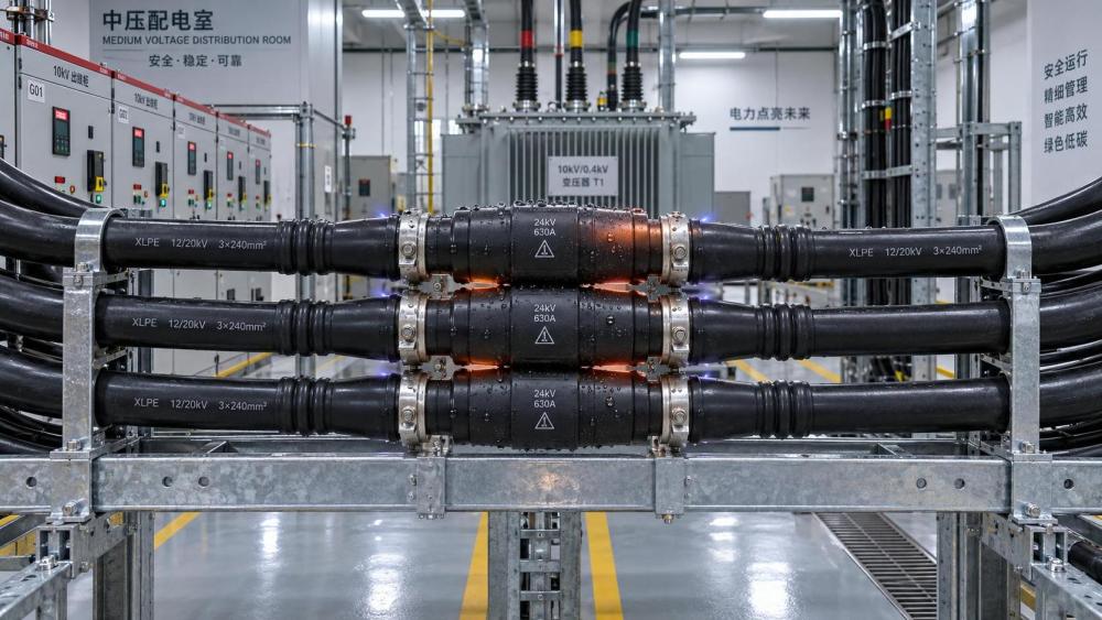
Water-related failures frequently appear around joints, transitions, and terminations. These are locations where multiple materials meet and where workmanship has a strong influence on sealing performance. A cable may be specified correctly while an accessory is incompatible with the cable construction, installed outside its approved dimensional range, or inadequately protected from water accumulation.
Mechanical damage can remain hidden until the cable is energized
Mechanical damage is often associated with excavation strikes, crushed ducts, and visibly cut cables. Those events are serious, but less obvious forms of damage are also important. Excessive pulling tension, a bend radius below the manufacturer’s limit, sidewall pressure at bends, sharp tray edges, or incorrect cleating can damage the conductor screen, insulation, metallic screen, or outer sheath without causing an immediate outage.
Damage introduced during installation may become a later reliability problem because a local defect concentrates electrical stress. A small indentation in insulation, a nick in a semiconductive screen, or deformation caused by over-tightened supports can create conditions for partial discharge or progressive electrical treeing. The cable can pass basic continuity checks and still retain a defect that becomes active after commissioning.
Movement after installation is another concern. Vibration near large motors, pumps, compressors, rail systems, or rotating machinery can fatigue terminations and support systems. Thermal expansion can pull against improperly restrained cable runs. In vertical installations, inadequate cleating may allow cable weight to load joints or terminations. These issues should be treated as mechanical-system problems, not only cable-material problems.
External damage can also compromise the oversheath without immediately reaching the main insulation. That distinction matters. A sheath defect may not cause an instant electrical fault, but it can permit moisture entry, expose metallic layers to corrosion, and set up a future insulation failure. For buried or submerged circuits, sheath integrity is therefore a useful early indicator of long-term condition.
Electrical stress exposes weak points
Every energized cable experiences electric-field stress, but the field should be controlled and distributed predictably through the insulation system. Failures become more likely where field geometry is disturbed: at damaged insulation, poorly prepared screen cuts, contaminated terminations, improperly installed stress-control components, voids in joints, or interfaces between incompatible materials.
Partial discharge is one of the clearest signs that localized electrical stress may be damaging insulation. It occurs when a small portion of insulation or a void discharges without immediately bridging the full insulation thickness. Repeated discharge can erode material, generate chemical by-products, and extend an electrical tree. It is more relevant in medium- and high-voltage systems, where accessory quality, cable construction, and test methods require careful technical control.
Voltage transients can add another layer of stress. Switching operations, capacitor-bank events, lightning-related surges, and converter-driven waveforms may expose weak insulation or unsuitable accessories. The correct response is not to assume that all variable-speed drives or power-electronic installations are inherently harmful to cables. The risk depends on the voltage class, cable length, grounding arrangement, motor or equipment interface, reflected-wave conditions, insulation design, and the protective measures used in the system.
For low-voltage installations, insulation failures often originate at points of poor workmanship, heat, abrasion, or contamination rather than from bulk dielectric aging alone. For medium-voltage and higher-voltage circuits, defects in screens, joints, terminations, and stress-control layers deserve more attention because small imperfections can have larger electrical consequences.
Contamination and chemicals degrade materials differently
Cable insulation and jackets are selected for expected exposure, yet site conditions can change after installation. Oils, fuels, solvents, acids, alkalis, cleaning agents, process dust, ozone, salt-laden air, and ultraviolet radiation can each affect polymeric materials in different ways. A cable with suitable electrical ratings may still be a poor fit for the chemical or environmental conditions around it.
PVC jackets can be vulnerable to certain chemicals and plasticizer loss; rubber-based compounds can swell or soften in incompatible oils; outdoor polymers can degrade under prolonged ultraviolet exposure if they are not formulated or protected for the application. The consequence may first appear as discoloration, embrittlement, cracking, swelling, or surface chalking. Once the outer protective layer degrades, inner metallic and insulating layers become more exposed to water and mechanical damage.
Contamination is also relevant at terminations. Dust combined with humidity, salt, or industrial deposits can form conductive paths across insulating surfaces. Tracking may then develop, particularly where electrical stress is high or drainage and sealing are poor. Cleaning alone may not resolve the issue if the termination design, creepage distance, enclosure condition, or environmental protection is inadequate.
Manufacturing defects and workmanship are not interchangeable
When insulation fails early, it is tempting to classify the event as a “bad cable.” That conclusion may be correct in some cases, but it should not be the default. The failed component might be the cable, a joint, a termination, a connector, an installation practice, or the operating environment. These causes require different corrective actions.
Manufacturing defects can include contamination, material irregularities, eccentric insulation thickness, conductor-screen imperfections, or defects introduced during handling and storage. Quality controls are intended to reduce these risks, but field evidence is required before assigning responsibility. Failure analysis should distinguish a defect that originated within the cable from a defect created by pulling, bending, terminating, testing, or operating the cable.
Accessory workmanship is particularly consequential because joints and terminations introduce interfaces that do not exist in a continuous factory-manufactured cable length. Preparation dimensions, screen removal, surface cleanliness, connector installation, torque control, stress-control placement, and sealing all affect performance. A technically sound accessory can fail if installed by a process that does not control those details.
How to investigate a cable insulation failure
A useful investigation begins with the event record, not with an assumption about the cause. Capture relay indications, fault current where available, load history, switching events, weather or flooding conditions, and the exact location of failure. Determine whether the circuit experienced a one-time fault, repeated alarms, falling insulation resistance, abnormal heating, or partial-discharge activity before the outage.
Then separate the cable system into sections: cable length, joints, terminations, connectors, protective devices, routing, and surrounding environment. A fault at a termination has a different evidence trail from a failure in the middle of a buried circuit. Physical inspection should look for heat discoloration, cracked or swollen jackets, moisture, tracking, corrosion, damaged screens, unusual bend geometry, loose supports, and signs of external impact.
Testing should be chosen for the voltage class, cable type, condition objective, and applicable site procedures. Insulation-resistance measurements can help identify gross deterioration or moisture-related problems, but they may not reveal every localized defect. Sheath testing can identify jacket damage. Partial-discharge assessment, dielectric testing, thermal imaging, and cable diagnostic methods may be appropriate where the system and risk justify them. Test results need to be interpreted with the cable’s construction, history, and accessory configuration in mind; a single reading without context can be misleading.
Where a failed section is removed, preserve it for examination rather than discarding it immediately. The failure origin can reveal whether the dominant mechanism was thermal, electrical, mechanical, water-related, chemical, or installation-related. That evidence is often more valuable than a generic replacement because it informs whether similar circuits elsewhere carry the same exposure.
Preventing recurrence requires matching the remedy to the cause
Replacing a failed cable without correcting the operating condition can simply restart the aging cycle. If overheating caused the damage, review load, conductor sizing, grouping, ambient conditions, thermal environment, and connection quality. If moisture is involved, inspect sheaths, ducts, drainage, joint seals, terminations, and cable-end handling. If the origin is electrical stress, focus on accessory compatibility, screen preparation, grounding and bonding arrangements, transient exposure, and the suitability of the test and commissioning process.
For asset owners, the most effective maintenance programs give extra attention to circuits with high consequence of failure and identifiable stress factors: continuously loaded feeders, wet or corrosive locations, poorly documented legacy installations, heavily modified tray systems, and circuits with repeated thermal or electrical anomalies. The goal is not to test every cable identically. It is to direct inspection and diagnostics toward the conditions most likely to shorten insulation life.
Power cable insulation failure is therefore best viewed as a system condition, not solely a material defect. Cable design remains important, but service life is shaped by installation quality, accessory control, thermal reality, environmental exposure, and the way the circuit is operated. Identifying which of those forces is active before the next fault is what turns a repair response into a reliability decision.
Related News
- What Causes Power Cable Insulation to Fail in Service?Sep 11, 2026What causes power cable insulation failure in service? Discover how heat, moisture, mechanical damage, electrical stress, and poor installation drive outages—and how to prevent them.
- Power Cables for Renewable Projects: Cost Drivers and Spec MistakesJul 10, 2026Power cables for renewable projects: uncover key cost drivers, common spec mistakes, and smarter selection tips to reduce losses, delays, and lifetime project risk.
- Terminal Block Product Information That Actually Matters in Design ReviewJun 30, 2026Electronics product information for terminal blocks should go beyond ratings. Learn what design reviews often miss, from derating and vibration to compliance and wiring reality.
- Hardcore Electrical Standards That Impact Site SafetyJun 08, 2026Hardcore electrical standards directly shape site safety, uptime, and compliance. Learn how grounding, protection, and cable control reduce risk across modern industrial facilities.
Related News
- 00
0000-00
How to verify suppliers listed in a power system supplier directory - 00
0000-00
What an intelligence portal for electronics industry should track - 00
0000-00
What to verify before choosing an energy storage system supplier - 00
0000-00
How electrical engineering for factories prevents costly downtime - 00
0000-00
When does a smart grid for buildings reduce peak demand charges?